LIGHTING SYSTEM Footwell Light Circuit
DESCRIPTION
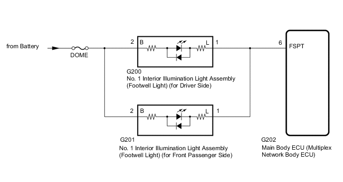
The main body ECU (multiplex network body ECU) controls the footwell lights.
WIRING DIAGRAM
CAUTION / NOTICE / HINT
Note
-
Inspect the fuses for circuits related to this system before performing the following procedure.
-
Before replacing the main ECU (multiplex network body ECU), refer to Service Bulletin.
-
Check that the "Inside Foot Light" customization setting is set to"ON".
PROCEDURE
-
PERFORM ACTIVE TEST USING GTS (FR FOOT LIGHT)
-
Using the GTS, perform the Active Test.
Body Electrical > Main Body > Active TestTester Display Measurement Item Control Range Diagnostic Note Fr Foot Light Footwell light ON or OFF -
Body Electrical > Main Body > Active TestTester Display Fr Foot Light OK Footwell lights comes on. Result Proceed to OK NG
OK 
PROCEED TO NEXT SUSPECTED AREA SHOWN IN PROBLEM SYMPTOMS TABLE Click here
NG 
-
-
CHECK HARNESS AND CONNECTOR (No. 1 INTERIOR ILLUMINATION LIGHT ASSEMBLY - BATTERY)
-
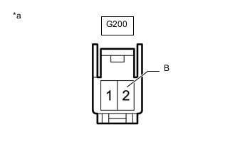
*a Front view of wire harness connector
(to No. 1 Interior Illumination Light Assembly [Footwell Light] [for Driver Side])
Disconnect the No. 1 interior illumination light assembly (footwell light) (for Driver Side) connector.
-
Disconnect the G201 No. 1 interior illumination light assembly (footwell light) (for Front passenger Side) connector.
-
Measure the voltage according to the value(s) in the table below.
Standard Voltage Tester Connection Condition Specified Condition G200-2 (B) - Battery Always 11 to 14 V Result Proceed to OK NG
NG
REPAIR OR REPLACE HARNESS OR CONNECTOR
OK
-
-
CHECK HARNESS AND CONNECTOR (No. 1 INTERIOR ILLUMINATION LIGHT ASSEMBLY - MAIN BODY ECU)
-
Disconnect the G200 No. 1 interior illumination light assembly (footwell light) (for Driver Side) connector.
-
Disconnect the G201 No. 1 interior illumination light assembly (footwell light) (for Front passenger Side) connector.
-
Disconnect the G202 main body ECU (multiplex network body ECU) connector.
-
Measure the resistance according to the value(s) in the table below.
Standard Resistance Tester Connection Condition Specified Condition G200-1 (L) - G202-6 (FSPT) Always Below 1 Ω G200-1 (L) or G202-6 (FSPT) - Body ground Always 10 kΩ or higher Result Proceed to OK NG
OK
REPLACE MAIN BODY ECU (MULTIPLEX NETWORK BODY ECU) for LHD: REPLACE MAIN BODY ECU (MULTIPLEX NETWORK BODY ECU) Click here
REPLACE MAIN BODY ECU (MULTIPLEX NETWORK BODY ECU) for RHD: REPLACE MAIN BODY ECU (MULTIPLEX NETWORK BODY ECU) Click hereNG
REPAIR OR REPLACE HARNESS OR CONNECTOR
-