BLOCKING SYSTEM, Diagnostic DTC:B1587
| DTC Code | DTC Name |
|---|---|
| B1587 | Lost Communication for Immobiliser Communication Circuit |
DESCRIPTION
When one of the following occurs: 1) the telephone transceiver assembly detects errors in its own communications with the certification ECU (smart key ECU assembly)*1 or transponder key ECU assembly*2, 2) the telephone transceiver assembly detects errors in the communication lines, or 3) the ECU communication ID between the certification ECU (smart key ECU assembly)*1 or transponder key ECU assembly*2 and telephone transceiver assembly is different and an engine start is attempted, the telephone transceiver assembly stores DTC B1587.
| DTC No. | Detection Item | DTC Detection Condition | Trouble Area |
|---|---|---|---|
| B1587 | Lost Communication for Immobiliser Communication Circuit |
Either condition is met: |
|
-
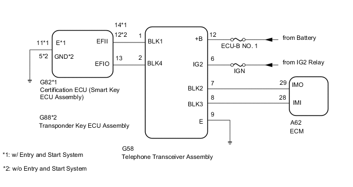
*1: w/ Entry and Start System
-
*2: w/o Entry and Start System
WIRING DIAGRAM
CAUTION / NOTICE / HINT
Note
-
Before troubleshooting for these DTCs, make sure no immobiliser system DTCs are output. If output, troubleshoot the immobiliser system DTCs first.
-
Inspect the fuses for circuits related to this system before performing the following inspection procedure.
-
When replacing the telephone transceiver assembly, certification ECU (smart key ECU assembly)*1 or transponder key ECU assembly*2, refer to the Service Bulletin.
-
When the telephone transceiver assembly is replaced, it is necessary to set the contract mode.
-
*1: w/ Entry and Start System
-
*2: w/o Entry and Start System
Tech Tips
-
When DTC B1587 and B2799 are output simultaneously, perform troubleshooting for DTC B2799 first.
-
After troubleshooting for this DTC, make sure B2799 is not output. If output, troubleshoot the blocking system DTCs next.
PROCEDURE
-
CHECK FOR DTC
-
Clear the DTCs.
Body Electrical > Telematics > Clear DTCs -
Turn the ignition switch off.
-
Start the engine.
-
Check for DTCs.
Body Electrical > Telematics > Clear DTCsResult Proceed to DTC B1587 is not output DTC B1587 is output
DTC B1587 is not output 
USE SIMULATION METHOD TO CHECK Click here
DTC B1587 is output 
-
-
PERFORM ECU COMMUNICATION ID
-
Reregister the ECU communication ID.
Tech Tips
Refer to the Service Bulletin.
Result Proceed to NEXT
NEXT
-
-
CHECK FOR DTC
-
Clear the DTCs.
Body Electrical > Telematics > Clear DTCs -
Turn the ignition switch off.
-
Start the engine.
-
Check for DTCs.
Body Electrical > Telematics > Trouble CodesResult Proceed to DTC B1587 is not output DTC B1587 is output
DTC B1587 is not output
END
DTC B1587 is output
-
-
CHECK CONNECTION OF CONNECTORS
-
Turn the ignition switch off.
-
Check that the connectors are properly connected to the telephone transceiver assembly and certification ECU (smart key ECU assembly)*1 or transponder key ECU assembly*2.
-
*1: w/ Entry and Start System
-
*2: w/o Entry and Start System
OK Connectors are properly connected. Result Proceed to OK (w/ Entry and Start System) OK (w/o Entry and Start System) NG -
OK (w/o Entry and Start System) 
CHECK HARNESS AND CONNECTOR (TELEPHONE TRANSCEIVER ASSEMBLY - TRANSPONDER KEY ECU ASSEMBLY) Click here
NG
CONNECT CONNECTORS CORRECTLY
OK (w/ Entry and Start System)
-
-
CHECK HARNESS AND CONNECTOR (TELEPHONE TRANSCEIVER ASSEMBLY - CERTIFICATION ECU [SMART KEY ECU ASSEMBLY])
-
Disconnect the G82 certification ECU (smart key ECU assembly) connector.
-
Disconnect the G58 telephone transceiver assembly connector.
-
Measure the resistance according to the value(s) in the table below.
Standard Resistance Tester Connection Condition Specified Condition G58-1 (BLK1) - G82-14 (EFII) Always Below 1 Ω G58-1 (BLK1) or G82-14 (EFII) - Body ground Always 10 kΩ or higher G58-2 (BLK4) - G82-13 (EFIO) Always Below 1 Ω G58-2 (BLK4) or G82-13 (EFIO) - Body ground Always 10 kΩ or higher -
Measure the voltage according to the value(s) in the table below.
Standard Voltage Tester Connection Condition Specified Condition G58-1 (BLK1) - Body ground Always Below 1 V G58-2 (BLK4) - Body ground Always Below 1 V Result Proceed to OK NG
NG
REPAIR OR REPLACE HARNESS OR CONNECTOR
OK
-
-
REPLACE CERTIFICATION ECU (SMART KEY ECU ASSEMBLY)
-
Replace the certification ECU (smart key ECU assembly) with a new one.
Tech Tips
Refer to the Service Bulletin.
Result Proceed to NEXT
NEXT
-
-
REGISTER ECU COMMUNICATION ID
-
Register the ECU communication ID.
Tech Tips
Refer to the Service Bulletin.
Result Proceed to NEXT
NEXT
-
-
CHECK FOR DTC
-
Clear the DTCs.
Body Electrical > Telematics > Clear DTCs -
Turn the engine switch off.
-
Start the engine.
-
Check for DTCs.
Body Electrical > Telematics > Trouble CodesResult Proceed to DTC B1587 is not output DTC B1587 is output
DTC B1587 is not output
END (CERTIFICATION ECU [SMART KEY ECU ASSEMBLY] WAS DEFECTIVE)
DTC B1587 is output
REPLACE TELEPHONE TRANSCEIVER ASSEMBLY
-
-
CHECK HARNESS AND CONNECTOR (TELEPHONE TRANSCEIVER ASSEMBLY - TRANSPONDER KEY ECU ASSEMBLY)
-
Disconnect the G88 transponder key ECU assembly connector.
-
Disconnect the G58 telephone transceiver assembly connector.
-
Measure the resistance according to the value(s) in the table below.
Standard Resistance Tester Connection Condition Specified Condition G58-1 (BLK1) - G88-12 (EFII) Always Below 1 Ω G58-1 (BLK1) or G88-12 (EFII) - Body ground Always 10 kΩ or higher G58-2 (BLK4) - G88-13 (EFIO) Always Below 1 Ω G58-2 (BLK4) or G88-13 (EFIO) - Body ground Always 10 kΩ or higher -
Measure the voltage according to the value(s) in the table below.
Standard Voltage Tester Connection Condition Specified Condition G58-1 (BLK1) - Body ground Always Below 1 V G58-2 (BLK4) - Body ground Always Below 1 V Result Proceed to OK NG
NG
REPAIR OR REPLACE HARNESS OR CONNECTOR
OK
-
-
REPLACE TRANSPONDER KEY ECU ASSEMBLY
-
Replace the transponder key ECU assembly with a new one.
Tech Tips
Refer to the Service Bulletin.
Result Proceed to NEXT
NEXT
-
-
REGISTER ECU COMMUNICATION ID
-
Register the ECU communication ID.
Tech Tips
Refer to the Service Bulletin.
Result Proceed to NEXT
NEXT
-
-
CHECK FOR DTC
-
Clear the DTCs.
Body Electrical > Telematics > Clear DTCs -
Turn the ignition switch off.
-
Start the engine.
-
Check for DTCs.
Body Electrical > Telematics > Trouble CodesResult Proceed to DTC B1587 is not output DTC B1587 is output
DTC B1587 is not output
END (TRANSPONDER KEY ECU ASSEMBLY WAS DEFECTIVE)
DTC B1587 is output
REPLACE TELEPHONE TRANSCEIVER ASSEMBLY
-