THEFT DETERRENT SYSTEM Glass Breakage Sensor Circuit
DESCRIPTION
When the glass breakage sensor detects that the back door glass, rear door quarter window glass LH or RH is tapped or broken, the sensor will set off the alarm for 30 seconds.
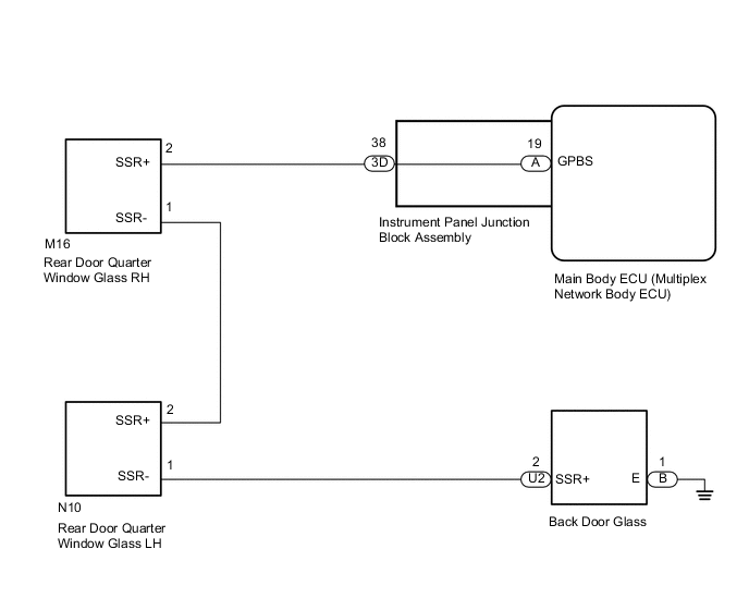
WIRING DIAGRAM
CAUTION / NOTICE / HINT
Note
When replacing the main body ECU (multiplex network body ECU), make sure to replace it with a new one.
PROCEDURE
-
READ VALUE USING GTS (GLASS BREAK SENSOR)
-
Connect the GTS to the DLC3.
-
Turn the ignition switch to ON.
-
Turn the GTS on.
-
Enter the following menus: Body Electrical / Main Body / Data List.
-
According to the display on the GTS, read the Data List.
Body Electrical > Main Body > Data ListTester Display Measurement Item Range Normal Condition Diagnostic Note Sealed Glas Brak Sen Glass breakage sensor connecting With or Without With: Glass breakage sensor connected
Without: Glass breakage sensor not connected
-
Body Electrical > Main Body > Data ListTester Display Sealed Glas Brak Sen OK "With" (glass breakage sensor operating) appears on GTS screen. Result Proceed to OK NG
OK 
REPLACE MAIN BODY ECU (MULTIPLEX NETWORK BODY ECU) Click here
NG 
-
-
CHECK HARNESS AND CONNECTOR (MAIN BODY ECU [MULTIPLEX NETWORK BODY ECU] - GLASS BREAKAGE SENSOR AND BODY GROUND)
-
Remove the main body ECU (multiplex network body ECU).
-
Connect the instrument panel junction block assembly connectors.
-
Disconnect the M16, N10, U2 and B glass breakage sensor connectors.
-
Measure the resistance according to the value(s) in the table below.
Standard Resistance Tester Connection Condition Specified Condition A-19 (GPBS) - M16-2 (SSR+) Always Below 1 Ω M16-1 (SSR-) - N10-2 (SSR+) Always Below 1 Ω N10-1 (SSR-) - U2-2 (SSR+) Always Below 1 Ω B-1 (E) - Body ground Always Below 1 Ω A-19 (GPBS) - Body ground Always 10 kΩ or higher M16-2 (SSR+) - Body ground Always 10 kΩ or higher M16-1 (SSR-) - Body ground Always 10 kΩ or higher N10-2 (SSR+) - Body ground Always 10 kΩ or higher N10-1 (SSR-) - Body ground Always 10 kΩ or higher U2-2 (SSR+) - Body ground Always 10 kΩ or higher Result Proceed to OK NG
NG 
CHECK HARNESS AND CONNECTOR (INSTRUMENT PANEL JUNCTION BLOCK ASSEMBLY - GLASS BREAKAGE SENSOR) Click here
OK
-
-
INSPECT REAR DOOR QUARTER WINDOW GLASS RH
-
Disconnect the M16 rear door quarter window glass RH connector.
-
Measure the resistance according to the value(s) in the table below.
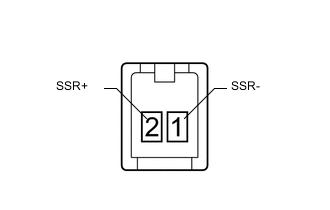
Standard Resistance Tester Connection Condition Specified Condition 2 (SSR+) - 1 (SSR-) Always Below 1 Ω Result Proceed to OK NG
NG
REPLACE REAR DOOR QUARTER WINDOW GLASS RH Click here
OK
-
-
INSPECT REAR DOOR QUARTER WINDOW GLASS LH
-
Disconnect the N10 rear door quarter window glass LH connector.
-
Measure the resistance according to the value(s) in the table below.
Standard Resistance Tester Connection Condition Specified Condition 2 (SSR+) - 1 (SSR-) Always Below 1 Ω Result Proceed to OK NG
NG
REPLACE REAR DOOR QUARTER WINDOW GLASS LH Click here
OK
-
-
INSPECT BACK DOOR GLASS
-
Disconnect the U2 and B back door glass connectors.
-
Measure the resistance according to the value(s) in the table below.
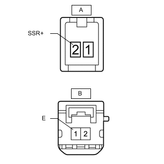
Standard Resistance Tester Connection Condition Specified Condition A-2 (SSR+) - B-1 (E) Always Below 1 Ω Result Proceed to OK NG
OK
REPLACE MAIN BODY ECU (MULTIPLEX NETWORK BODY ECU) Click here
NG
REPLACE BACK DOOR GLASS Click here
-
-
CHECK HARNESS AND CONNECTOR (INSTRUMENT PANEL JUNCTION BLOCK ASSEMBLY - GLASS BREAKAGE SENSOR)
-
Disconnect the 3D instrument panel junction block assembly connector.
-
Disconnect the M16 glass breakage sensor connector.
-
Measure the resistance according to the value(s) in the table below.
Standard Resistance Tester Connection Condition Specified Condition 3D-38 (GCS) - M16-2 (SSR+) Always Below 1 Ω 3D-38 (GCS) - Body ground Always 10 kΩ or higher M16-2 (SSR+) - Body ground Always 10 kΩ or higher Result Proceed to OK NG
OK
REPLACE INSTRUMENT PANEL JUNCTION BLOCK ASSEMBLY
NG
REPAIR OR REPLACE HARNESS OR CONNECTOR
-