THEFT DETERRENT SYSTEM, Diagnostic DTC:B2769
| DTC Code | DTC Name |
|---|---|
| B2769 | Tilt Sensor Signal Circuit Malfunction |
DESCRIPTION
This DTC is stored when one of the following occurs: 1) tilt sensor (yaw rate sensor assembly) power supply malfunction; 2) tilt sensor (yaw rate sensor assembly) open malfunction; or 3) EEPROM malfunction.
| DTC No. | Detection Item | DTC Detection Condition | Trouble Area |
|---|---|---|---|
| B2769 | Tilt Sensor Signal Circuit Malfunction |
If one of the following is detected: |
|
WIRING DIAGRAM
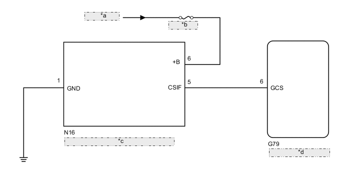
| *a | from Battery |
| *b | ECU-B NO.1 |
| *c | Tilt Sensor (Yaw Rate Sensor Assembly) |
| *d | Main Body ECU (Multiplex Network Body ECU) |
CAUTION / NOTICE / HINT
Note
-
Inspect the fuses for circuits related to this system before performing the following inspection procedure.
-
When replacing the main body ECU (multiplex network body ECU), make sure to replace it with a new one.
PROCEDURE
-
CHECK HARNESS AND CONNECTOR (TILT SENSOR [YAW RATE SENSOR ASSEMBLY] - BATTERY AND BODY GROUND)
-
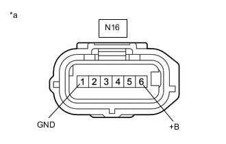
*a Front view of wire harness connector
(to Tilt Sensor [Yaw Rate Sensor Assembly])
Disconnect the tilt sensor (yaw rate sensor assembly) connector.
-
Measure the voltage according to the value(s) in the table below.
Standard Voltage Tester Connection Condition Specified Condition N16-6 (+B) - Body ground Always 11 to 14 V -
Measure the resistance according to the value(s) in the table below.
Standard Resistance Tester Connection Condition Specified Condition N16-1 (GND) - Body ground Always Below 1 Ω Result Proceed to OK NG
NG 
REPAIR OR REPLACE HARNESS OR CONNECTOR
OK 
-
-
CHECK HARNESS AND CONNECTOR (MAIN BODY ECU [MULTIPLEX NETWORK BODY ECU] - TILT SENSOR [YAW RATE SENSOR ASSEMBLY])
-
Disconnect the G79 main body ECU (multiplex network body ECU) connector.
-
Disconnect the N16 tilt sensor (yaw rate sensor assembly) connector.
-
Measure the resistance according to the value(s) in the table below.
Standard Resistance Tester Connection Condition Specified Condition G79-6 (GCS) - N16-5 (CSIF) Always Below 1 Ω G79-6 (GCS) - Body ground Always 10 kΩ or higher N16-5 (CSIF) - Body ground Always 10 kΩ or higher Result Proceed to OK NG
NG
REPAIR OR REPLACE HARNESS OR CONNECTOR
OK
-
-
CHECK WAVEFORM (TILT SENSOR [YAW RATE SENSOR ASSEMBLY]) (CSIF)
-
Using an oscilloscope, check the waveform.
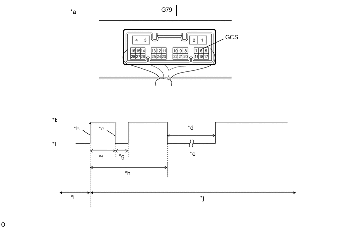
*a Component with harness connected
(Main Body ECU [Multiplex Network Body ECU])
*b CSIF Initial Signal *c CSIF Initial Response *d Approximately 1.0 seconds *e Initial Diagnosis *f Approximately 1.0 to 1.6 seconds *g Approximately 0.05 seconds *h Approximately 5.5 seconds *i Disarmed State *j Arming Preparation State *k HI *l LO Measurement Condition Tester Connection Content Tester Connection G79-6 (GCS) - Body ground Tool Setting 2 V/DIV., 100 ms./DIV. Condition Theft deterrent system is set (system changes from disarmed state to arming preparation state) Tech Tips
-
If the tilt sensor (yaw rate sensor assembly) is normal, an initial response is output in response to the HI input from the main body ECU (multiplex network body ECU).
-
If the waveform output remains LO, there may be a problem with the main body ECU (multiplex network body ECU), as there is no input from the main body ECU (multiplex network body ECU).
OK The waveform displays properly (HI is 6.5 V or higher and LO is below 1 V). Result Result Proceed to NG (Waveform output remains LO) A NG (There is no initial response and the waveform output remains HI) B OK (There is an initial response) C -
A
REPLACE MAIN BODY ECU (MULTIPLEX NETWORK BODY ECU) Click here
B
REPLACE TILT SENSOR (YAW RATE SENSOR ASSEMBLY) Click here
C
USE SIMULATION METHOD TO CHECK Click here
-