KEY REMINDER WARNING SYSTEM TERMINALS OF ECU
-
CHECK INSTRUMENT PANEL JUNCTION BLOCK ASSEMBLY AND MAIN BODY ECU (MULTIPLEX NETWORK BODY ECU)
-
Remove the main body ECU (multiplex network body ECU).
-
for LHD:
-
for RHD:
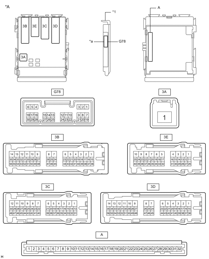
*A Main body ECU (multiplex network body ECU) with 1 connector - - *1 Main body ECU (multiplex network body ECU) - - *a 1 connector - - 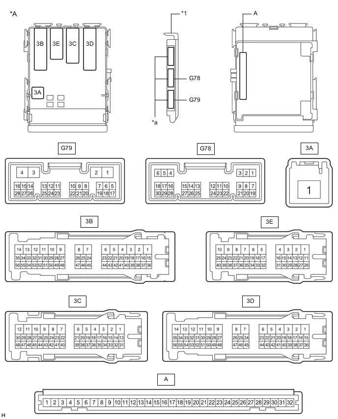
*A Main body ECU (multiplex network body ECU) with 3 connectors - - *1 Main body ECU (multiplex network body ECU) - - *a 3 connectors - - -
-
Measure the resistance according to the value(s) in the table below.
Tester Connection Wiring Color Terminal Description Condition Specified Condition A-11 (GND1) - Body ground - Ground Always Below 1 Ω A-2 (FLCY) - Body ground*1 - Driver door courtesy light switch input Driver door open Below 1 Ω A-2 (FLCY) - Body ground*1 - Driver door courtesy light switch input Driver door closed 10 kΩ or higher G78-19 (FRCY) - Body ground*2 L - Body ground Driver door courtesy light switch input Driver door open Below 1 Ω G78-19 (FRCY) - Body ground*2 L - Body ground Driver door courtesy light switch input Driver door closed 10 kΩ or higher G78-17 (KSW) - Body ground R - Body ground Unlock warning switch signal No key in ignition key cylinder 10 kΩ or higher G78-17 (KSW) - Body ground R - Body ground Unlock warning switch signal Key in ignition key cylinder Below 1 Ω *1: for LHD
*2: for RHD
If the result is not as specified, there may be a malfunction on the wire harness side.
-