POWER DOOR LOCK CONTROL SYSTEM Collision Door Lock Release Function does not Operate
DESCRIPTION
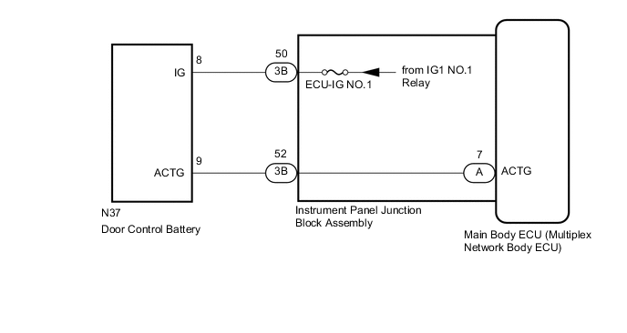
When an impact is detected, a relay inside the door control battery is operated to switch the power source of the door lock with motor assemblies from the vehicle battery to the door control battery.
WIRING DIAGRAM
CAUTION / NOTICE / HINT
Note
-
When replacing the main body ECU (multiplex network body ECU), make sure to replace it with a new one.
-
As the door control battery is installed between the vehicle battery and main body ECU (multiplex network body ECU), first perform the inspections in On-Vehicle Inspection to confirm that there are no malfunctions in the power source circuit for the main body ECU (multiplex network body ECU) before performing this troubleshooting procedure.
PROCEDURE
-
CHECK DOOR LOCK OPERATION
-
Check door lock operation.
OK All doors lock and unlock normally. Result Proceed to OK NG
NG 
GO TO PROBLEM SYMPTOMS TABLE Click here
OK 
-
-
CHECK DOOR CONTROL BATTERY (BATTERY VOLTAGE)
-
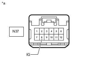
*a Front view of wire harness connector
(to Door Control Battery)
Disconnect the door control battery connector.
-
Measure the voltage according to the value(s) in the table below.
Standard Voltage Tester Connection Switch Condition Specified Condition N37-8 (IG) - Body ground Engine switch on (IG) 11 to 14 V Result Proceed to OK NG
NG 
CHECK HARNESS AND CONNECTOR (INSTRUMENT PANEL JUNCTION BLOCK ASSEMBLY - DOOR CONTROL BATTERY) Click here
OK
-
-
CHECK HARNESS AND CONNECTOR (INSTRUMENT PANEL JUNCTION BLOCK ASSEMBLY - DOOR CONTROL BATTERY)
-
Disconnect the 3B instrument panel junction block assembly connector.
-
Disconnect the N37 door control battery connector.
-
Measure the resistance according to the value(s) in the table below.
Standard Resistance Tester Connection Condition Specified Condition 3B-52 (ACTG) - N37-9 (ACTG) Always Below 1 Ω 3B-52 (ACTG) or N37-9 (ACTG) - Body ground Always 10 kΩ or higher Result Proceed to OK NG
NG
REPAIR OR REPLACE HARNESS OR CONNECTOR
OK
-
-
INSPECT INSTRUMENT PANEL JUNCTION BLOCK ASSEMBLY
-
Remove the instrument panel junction block assembly.
for LHD: Click here
for RHD: Click here
-
Remove the main body ECU (multiplex network body ECU) from the instrument panel junction block assembly.
-
Measure the resistance according to the value(s) in the table below.
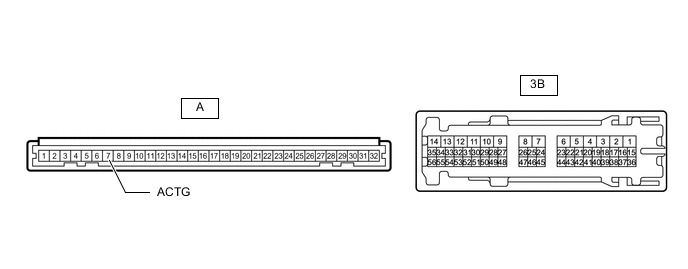
*a Component without harness connected
(Instrument Panel Junction Block Assembly)
- - Standard Resistance Tester Connection Condition Specified Condition A-7 (ACTG) - 3B-52 Always Below 1 Ω Result Proceed to OK NG
NG
REPLACE INSTRUMENT PANEL JUNCTION BLOCK ASSEMBLY for LHD: Click here for RHD: Click here
OK
-
-
REPLACE DOOR CONTROL BATTERY
-
Replace the door control battery with a new or known good one.
Result Proceed to NEXT
NEXT
-
-
CHECK DOOR CONTROL BATTERY
-
Check door control battery operation.
OK Collision detection door lock function operates normally. Result Proceed to OK NG
OK
END (DOOR CONTROL BATTERY WAS DEFECTIVE)
NG
REPLACE MAIN BODY ECU (MULTIPLEX NETWORK BODY ECU) for LHD: Click here for RHD: Click here
-
-
CHECK HARNESS AND CONNECTOR (INSTRUMENT PANEL JUNCTION BLOCK ASSEMBLY - DOOR CONTROL BATTERY)
-
Disconnect the 3B instrument panel junction block assembly connector.
-
Disconnect the N37 door control battery connector.
-
Measure the resistance according to the value(s) in the table below.
Standard Resistance Tester Connection Condition Specified Condition 3B-50 - N37-8 (IG) Always Below 1 Ω 3B-50 or N37-8 (IG) - Body ground Always 10 kΩ or higher Result Proceed to OK NG
NG
REPAIR OR REPLACE HARNESS OR CONNECTOR
OK
-
-
CHECK INSTRUMENT PANEL JUNCTION BLOCK ASSEMBLY (BATTERY VOLTAGE)
-
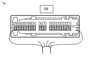
*a Component with harness connected
(Instrument Panel Junction Block Assembly)
Disconnect the instrument panel junction block assembly.
-
Measure the voltage according to the value(s) in the table below.
Standard Voltage Tester Connection Switch Condition Specified Condition 3B-50 - Body ground Engine switch on (IG) 11 to 14 V Result Proceed to OK NG
OK
REPLACE INSTRUMENT PANEL JUNCTION BLOCK ASSEMBLY for LHD: Click here for RHD: Click here
NG
GO TO LIGHTING SYSTEM (IG Signal Circuit) Click here
-