FRONT POWER SEAT CONTROL SYSTEM(w/ Memory) TERMINALS OF ECU
-
CHECK POSITION CONTROL ECU AND SWITCH ASSEMBLY (for LHD)
-
Disconnect the e18 and e6 position control ECU and switch assembly connectors.

-
Measure the voltage and resistance according to the value(s) in the table below.
Terminal Connection Wiring Color Terminal Description Condition Specified Condition e18-2 (GND1) - Body ground W-B - Body ground Ground Always Below 1 Ω e18-7 (+B1) - e18-2 (GND) W - W-B Battery supply Always 11 to 14 V e6-3 (IG) - e18-2 (GND) R - W-B IG power supply Ignition switch off Below 1 V Ignition switch ON 11 to 14 V e6-12 (SYSB) - e18-2 (GND) P - W-B System power supply Always 11 to 14 V -
Reconnect the e18 and e6 position control ECU and switch assembly connectors.
-
Measure the voltage and resistance according to the value(s) in the table below.
Terminal Connection Wiring Color Terminal Description Condition Specified Condition e18-6 (+B2) - e18-1 (GND2) SB - W-B Lumbar support adjuster power source Always 11 to 14 V e18-1 (GND2) - Body ground W-B - Body ground Lumbar support adjuster ground Always Below 1 Ω e18-3 (SLD+) - e18-2 (GND1) L - W-B Slide motor signal (forward) Slide switch off Below 1 V Slide switch on (Forward) 11 to 14 V e18-4 (SLD-) - e18-2 (GND1) GR - W-B Slide motor signal (rearward) Slide switch off Below 1 V Slide switch on (Rearward) 11 to 14 V e18-5 (FRV-) - e18-2 (GND1) R - W-B Front vertical motor signal (downward) Front vertical switch off Below 1 V Front vertical switch on (Downward) 11 to 14 V e18-8 (FRV+) - e18-2 (GND1) B - W-B Front vertical motor signal (upward) Front vertical switch off Below 1 V Front vertical switch on (Upward) 11 to 14 V e18-9 (RCL+) - e18-2 (GND1) P - W-B Reclining motor signal (forward) Reclining switch off Below 1 V Reclining switch on (Forward) 11 to 14 V e18-11 (RCL-) - e18-2 (GND1) LG - W-B Reclining motor signal (rearward) Reclining switch off Below 1 V Reclining switch on (Rearward) 11 to 14 V e18-10 (LFT+) - e18-2 (GND1) V - W-B Lifter motor signal (upward) Lifter switch off Below 1 V Lifter switch on (Upward) 11 to 14 V e18-12 (LFT-) - e18-2 (GND1) G - W-B Lifter motor signal (downward) Lifter switch off Below 1 V Lifter switch on (Downward) 11 to 14 V
-
-
CHECK POSITION CONTROL ECU AND SWITCH ASSEMBLY (for RHD)
-
Disconnect the d27 and d28 position control ECU and switch assembly connectors.

-
Measure the voltage and resistance according to the value(s) in the table below.
Terminal Connection Wiring Color Terminal Description Condition Specified Condition d27-2 (GND1) - Body ground W-B - Body ground Ground Always Below 1 Ω d27-7 (+B1) - d27-2 (GND1) W - W-B Battery supply Always 11 to 14 V d28-3 (IG) - d27-2 (GND) R - W-B IG power supply Ignition switch off Below 1 V Ignition switch ON 11 to 14 V d28-12 (SYSB) - d27-2 (GND) P - W-B System power supply Always 11 to 14 V -
Reconnect the d27 and d28 position control ECU and switch assembly connectors.
-
Measure the voltage and resistance according to the value(s) in the table below.
Terminal Connection Wiring Color Terminal Description Condition Specified Condition d27-6 (+B2) - d27-1 (GND2) SB - W-B Lumbar support adjuster power source Always 11 to 14 V d27-1 (GND2) - Body ground W-B - Body ground Lumbar support adjuster ground Always Below 1 Ω d27-3 (SLD+) - d27-2 (GND1) L - W-B Slide motor signal (forward) Slide switch off Below 1 V Slide switch on (Forward) 11 to 14 V d27-4 (SLD-) - d27-2 (GND1) GR - W-B Slide motor signal (rearward) Slide switch off Below 1 V Slide switch on (Rearward) 11 to 14 V d27-5 (FRV-) - d27-2 (GND1) R - W-B Front vertical motor signal (downward) Front vertical switch off Below 1 V Front vertical switch on (Downward) 11 to 14 V d27-8 (FRV+) - d27-2 (GND1) B - W-B Front vertical motor signal (upward) Front vertical switch off Below 1 V Front vertical switch on (Upward) 11 to 14 V d27-9 (RCL+) - d27-2 (GND1) P - W-B Reclining motor signal (forward) Reclining switch off Below 1 V Reclining switch on (Forward) 11 to 14 V d27-11 (RCL-) - d27-2 (GND1) LG - W-B Reclining motor signal (rearward) Reclining switch off Below 1 V Reclining switch on (Rearward) 11 to 14 V d27-10 (LFT+) - d27-2 (GND1) V - W-B Lifter motor signal (upward) Lifter switch off Below 1 V Lifter switch on (Upward) 11 to 14 V d27-12 (LFT-) - d27-2 (GND1) G - W-B Lifter motor signal (downward) Lifter switch off Below 1 V Lifter switch on (Downward) 11 to 14 V
-
-
CHECK MAIN BODY ECU (MULTIPLEX NETWORK BODY ECU) AND INSTRUMENT PANEL JUNCTION BLOCK ASSEMBLY
-
Remove the main body ECU (multiplex network body ECU).
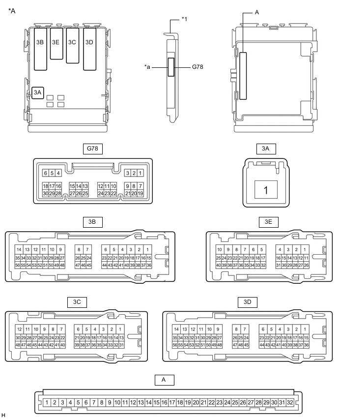
*A Main Body ECU (Multiplex Network Body ECU) with 1 Connector - - *1 Main Body ECU (Multiplex Network Body ECU) - - *a 1 Connector - - 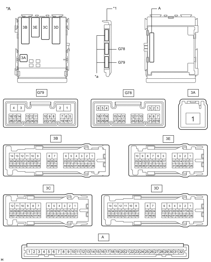
*A Main Body ECU (Multiplex Network Body ECU) with 3 Connectors - - *1 Main Body ECU (Multiplex Network Body ECU) - - *a 3 Connectors - - -
Measure the voltage and resistance according to the value(s) in the table below.
Terminal Connection Wiring Color Terminal Description Condition Specified Condition A-30 (BECU) - Body ground - Battery power supply Always 11 to 14 V A-32 (IG) - Body ground - IG power supply Ignition switch ON 11 to 14 V*1
10.5 to 14 V*2
A-32 (IG) - Body ground - IG power supply Ignition switch off Below 1 V A-29 (ACC) - Body ground - ACC power supply Ignition switch ACC 11 to 14 V A-29 (ACC) - Body ground - ACC power supply Ignition switch off Below 1 V A-11 (GND1) - Body ground - Ground Always Below 1 Ω
-
*1: w/o Stop and Start System
-
*2: w/ Stop and Start System
-
-
Install the main body ECU (multiplex network body ECU).
-
Measure the voltage and check for pulses according to the value(s) in the table below.
Tester Connection Wiring Color Terminal Description Condition Specified Condition G78-19 (FRCY) - Body ground*1 L - Body ground Front door courtesy light switch RH input Front door RH open Below 1 V Front door RH closed Pulse generation 3E-40 (FLCY) - Body ground*2 W - Body ground Front door courtesy light switch LH input Front door LH open Below 1 V Front door LH closed Pulse generation
-
*1: for RHD
-
*2: for LHD
-
-