PRE-CRASH SAFETY SYSTEM TERMINALS OF ECU
-
CHECK DRIVING SUPPORT ECU ASSEMBLY

-
Disconnect the G168 driving support ECU assembly connector.
Note
If a load of more than 10 kg (22 lb) is placed on the connector, it may break. Do not place more load than is necessary on the connector.
-
Measure the voltage and resistance according to the value(s) in the table below.
Terminal No. (Symbol) Wiring Color Terminal Description Condition Specified Condition G168-28 (GND) - Body ground BR - Body ground Ground Always Below 1 Ω G168-7 (B) - Body ground B - Body ground*1
V - Body ground*2
Power source Ignition switch ON 11 to 14 V*1
9.5 to 14 V*2
Ignition switch off Below 1 V *1: w/o Stop and Start System
*2: w/ Stop and Start System
Tech Tips
If the result is not as specified, there may be a malfunction on the wire harness side.
-
Reconnect the G168 driving support ECU assembly connector.
-
Check for pulses according to the value(s) in the table below.
Terminal No. (Symbol) Wiring Color Terminal Description Condition Specified Condition G168-3 (BZ) - Body ground LG - Body ground Skid control buzzer output Ignition switch ON
Skid control buzzer operating
0 to 1.5 V Ignition switch ON
Skid control buzzer not operating
11 to 14 V*1
9.5 to 14 V*2
G168-11 (CA2L) - G168-28 (GND) LG - BR CAN communication signal Ignition switch ON Pulse generation
(See waveform 1)
G168-9 (CA1N) - G168-28 (GND) W - BR CAN communication signal Ignition switch ON Pulse generation
(See waveform 2)
G168-10 (CA2H) - G168-28 (GND) P - BR CAN communication signal Ignition switch ON Pulse generation
(See waveform 3)
G168-8 (CA1P) - G168-28 (GND) B - BR CAN communication signal Ignition switch ON Pulse generation
(See waveform 4)
*1: w/o Stop and Start System
*2: w/ Stop and Start System
-
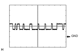
Waveform 1
-
CAN communication signal
Item Content Tester Connection G168-11 (CA2L) - G168-28 (GND) Tool Setting 1 V/DIV., 10 μsec./DIV. Condition Ignition switch ON Tech Tips
The waveform varies depending on the CAN communication signal.
-
-
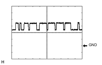
Waveform 2
-
CAN communication signal
Item Content Tester Connection G168-9 (CA1N) - G168-28 (GND) Tool Setting 1 V/DIV., 10 μsec./DIV. Condition Ignition switch ON Tech Tips
The waveform varies depending on the CAN communication signal.
-
-
Waveform 3
-
CAN communication signal
Item Content Tester Connection G168-10 (CA2H) - G168-28 (GND) Tool Setting 1 V/DIV., 10 μsec./DIV. Condition Ignition switch ON Tech Tips
The waveform varies depending on the CAN communication signal.
-
-
Waveform 4
-
CAN communication signal
Item Content Tester Connection G168-8 (CA1P) - G168-28 (GND) Tool Setting 1 V/DIV., 10 μsec./DIV. Condition Ignition switch ON Tech Tips
The waveform varies depending on the CAN communication signal.
-
-
-
CHECK MILLIMETER WAVE RADAR SENSOR ASSEMBLY
-
CHECK FORWARD RECOGNITION CAMERA
-
CHECK BRAKE ACTUATOR ASSEMBLY (SKID CONTROL ECU)