SPIRAL CABLE(for Single Type) INSTALLATION
CAUTION / NOTICE / HINT
Tech Tips
-
Use the same procedure for the driver side of RHD and LHD vehicles.
-
The procedures listed below are for the driver side of LHD vehicles.
PROCEDURE
-
INSTALL SPIRAL CABLE SUB-ASSEMBLY
Note
-
Do not replace the spiral cable sub-assembly with the battery connected and the ignition switch on (IG).
-
Do not rotate the spiral cable sub-assembly with the battery connected and the ignition switch on (IG).
-
Ensure that the steering wheel is installed and aligned straight when inspecting the steering sensor.
-
Check that the ignition switch is off.
-
Check that the cable is disconnected from the negative (-) battery terminal.
CAUTION:
Wait at least 90 seconds after disconnecting the cable from the negative (-) battery terminal to disable the SRS system.
-
Check that the front wheels are facing straight ahead.
-
Attach the 3 claws to install the spiral cable sub-assembly.
Note
When replacing the spiral cable sub-assembly with a new one, remove the lock pin before installing the steering wheel assembly.
-
Connect the connector to the spiral cable sub-assembly.
Note
When connecting any airbag connector, take care not to damage the airbag wire harness.
-
-
INSTALL STEERING COLUMN COVER
-
TURN FRONT WHEELS TO FACE STRAIGHT AHEAD
-
ADJUST SPIRAL CABLE SUB-ASSEMBLY
Note
Do not adjust the spiral cable with the battery connected and the ignition switch on (IG).
-
Check that the ignition switch is off.
-
Check that the cable is disconnected from the negative (-) battery terminal.
CAUTION:
Wait at least 90 seconds after disconnecting the cable from the negative (-) battery terminal to disable the SRS system.
-
Check the check window shown in the illustration.
Tech Tips
When the spiral cable sub-assembly is centered, the connector is at the top and the conditions below can be checked.
-
w/o Steering Heater:
With the steering wheel straight ahead, align the matchmarks to check the colored roller from the check window.
-
w/ Steering Heater:
With the steering wheel straight ahead, align the matchmarks to check the U-turn point of the cable from the check window.
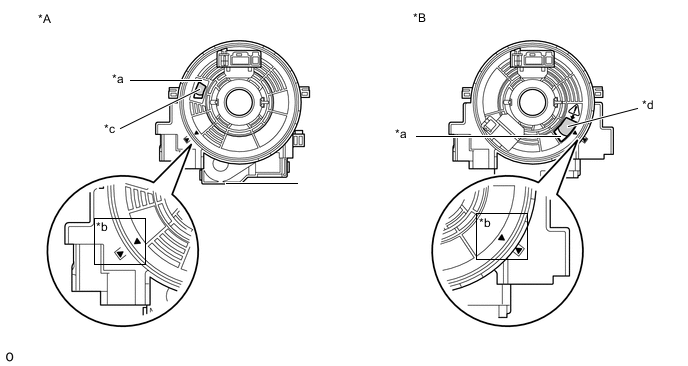
*A w/o Steering Heater *B w/ Steering Heater *a Check Window *b Matchmark *c Colored Roller *d U-turn Point -
-
If the spiral cable sub-assembly is not centered, center it.
-
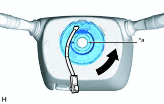
*a Interlock While pushing on the interlock indicated in the illustration, rotate the spiral cable sub-assembly counterclockwise slowly by hand until it stops.
Note
-
When rotating the spiral cable sub-assembly , make sure to push on the interlock indicated in the illustration to release the interlock mechanism.
-
Do not turn the spiral cable sub-assembly using the airbag wire harness.
-
-
Rotate the spiral cable sub-assembly 2.5 times clockwise from the lock position and check the check window.
Tech Tips
-
The spiral cable sub-assembly will rotate approximately 2.5 turns to both the left and right from the center.
-
When the spiral cable sub-assembly is centered, the connector is at the top and the conditions below can be checked.
-
w/o Steering Heater:
With the steering wheel straight ahead, align the matchmarks to check the colored roller from the check window.
-
w/ Steering Heater:
With the steering wheel straight ahead, align the matchmarks to check the U-turn point of the cable from the check window.
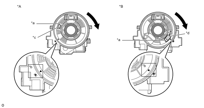
*A w/o Steering Heater *B w/ Steering Heater *a Check Window *b Matchmark *c Colored Roller *d U-turn Point 
Interlock - - If the cable cannot be centered, it is possible that the spiral cable sub-assembly is broken. Replace the spiral cable sub-assembly with a new one.
-
-
-
-
INSTALL STEERING WHEEL ASSEMBLY
-
CONNECT CABLE TO NEGATIVE BATTERY TERMINAL
Note
When disconnecting the cable, some systems need to be initialized after the cable is reconnected.
-
PERFORM DIAGNOSTIC SYSTEM CHECK
-
CHECK SRS WARNING LIGHT