CAN COMMUNICATION SYSTEM(for RHD) SYSTEM DIAGRAM
-
SYSTEM DIAGRAM
-
Overall CAN Bus Diagram
-
Control system CAN is composed of 5 buses.
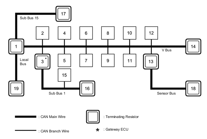
No. ECU/Sensor Name 1 ECM 2 Air conditioning amplifier assembly 3 Main body ECU (multiplex network body ECU) 4 Brake actuator assembly (skid control ECU) 5 Power steering ECU assembly 6 Spiral with sensor cable sub-assembly (steering angle sensor) 7 DLC3 8 Airbag sensor assembly 9 4WD ECU assembly*1 10 Engine start and stop ECU*2 11
-
Radio and display receiver assembly*3
-
Navigation ECU sub-assembly*4
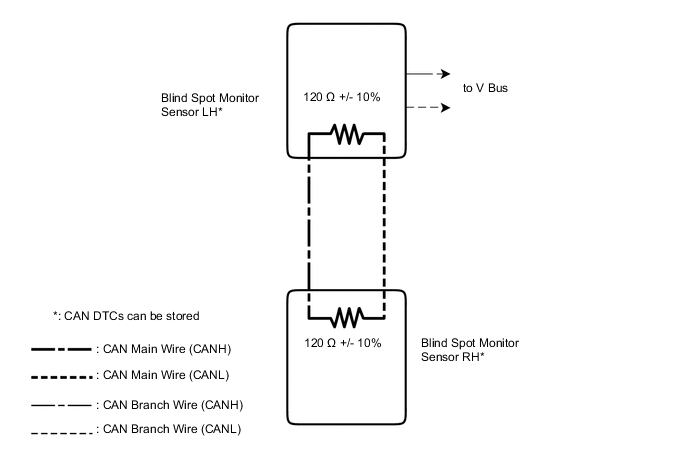
12 Certification ECU (smart key ECU assembly)*5 13 Blind spot monitor sensor LH*6 14 Combination meter assembly 15 Multiplex network door ECU*7 16 No. 6 CAN junction connector 17
-
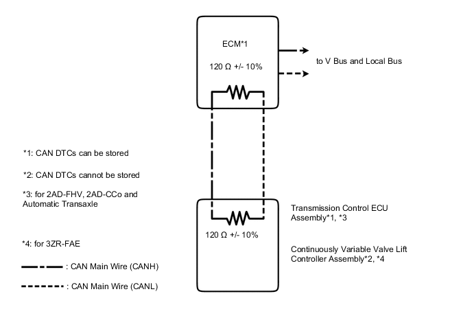
Transmission control ECU assembly*8
-
Continuously variable valve lift controller assembly*9
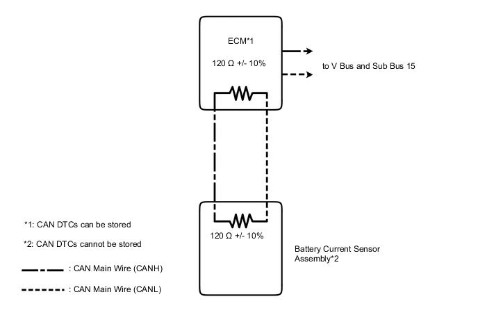
18 Blind spot monitor sensor RH*1 19 Battery current sensor assembly*10 *1: for 4WD/AWD
*2: w/ Stop and Start System
*3: for Radio and Display Type
*4: for Navigation Receiver Type
*5: w/ Entry and Start System
*6: w/ Blind Spot Monitor System
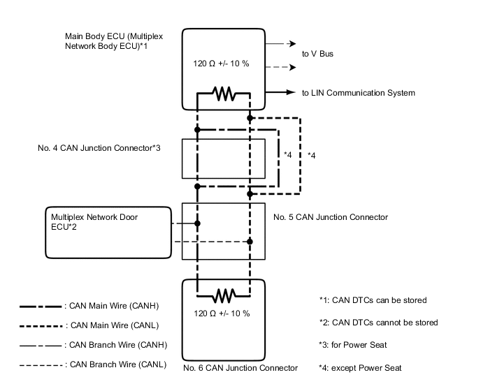
*7: w/ Power Back Door System
*8: for 2AD-FHV, 2AD-CCo and Automatic Transaxle
*9: for 3ZR-FAE
*10: for 3ZR-FAE, 1AD-FTV
Tech Tips
-
The main body ECU (multiplex network body ECU) functions as a gateway between the V bus and sub bus 1.
-
Refer to the following bus wiring diagrams for details.
-
-
-
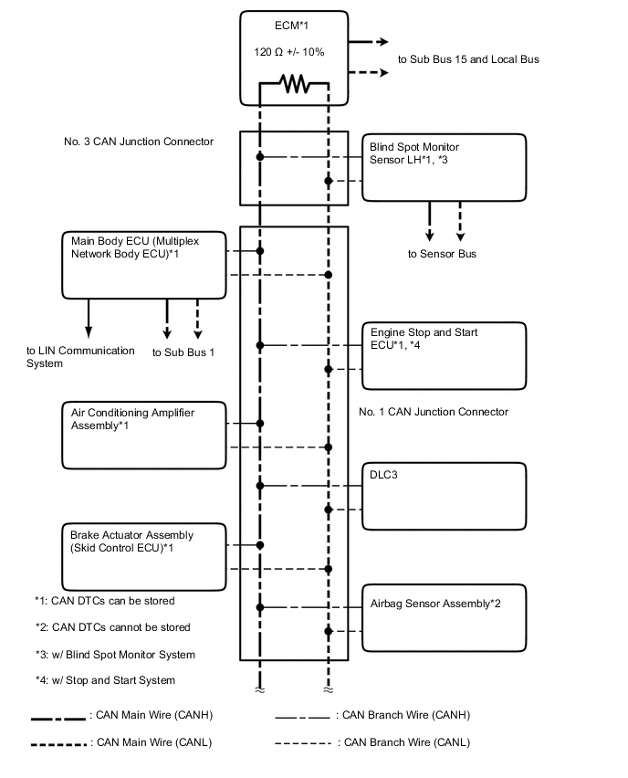
V Bus
Tech Tips
The CAN communication system connects to other networks via ECUs that function as a gateway.
-
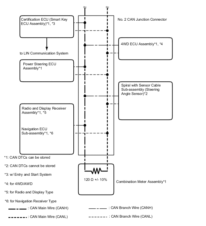
Sub Bus 1 (w/ Power Back Door System)
Tech Tips
The CAN communication system connects to other networks via ECUs that function as a gateway.
-
Sub Bus 15
-
Sensor Bus (w/ Blind Spot Monitor System)
-
Local Bus (for 3ZR-FAE or 1AD-FTV)
-