CAN COMMUNICATION SYSTEM(for LHD) TERMINALS OF ECU
Tech Tips
Operating the ignition switch, any switches or any doors triggers related ECU and sensor communication with the CAN, which causes resistance variation.
-
DISCONNECT CABLE FROM NEGATIVE BATTERY TERMINAL
-
Disconnect the cable from the negative (-) battery terminal before measuring the resistances of the CAN main wire and the CAN branch wire.
CAUTION:
Wait at least 90 seconds after disconnecting the cable from the negative (-) battery terminal to disable the SRS system.
Note
-
Before measuring the resistance, leave the vehicle for at least 1 minute and do not operate the ignition switch, any switches or any doors. If doors need to be opened in order to check connectors, open the doors and leave them open.
-
After turning the cable disconnected from negative (-) battery terminal, waiting time may be required before disconnecting the cable from the battery terminal. Therefore, make sure to read the disconnecting the cable from the battery terminal notice before proceeding with work.
-
When disconnecting the cable, some systems need to be initialized after the cable is reconnected.
-
-
-
JUNCTION CONNECTOR
-
No. 1 CAN Junction Connector
Tech Tips
Connectors that connect to the No. 1 CAN junction connector can be distinguished by the color of their CAN bus wires. When the connectors have been disconnected from the CAN junction connector, reconnecting the connectors to non-original positions on the CAN junction connector does not affect system performance. However, it is preferred to reconnect the connectors to their original positions to avoid negative effects on the wiring such as tension on the wiring harnesses, and to make future maintenance easier.
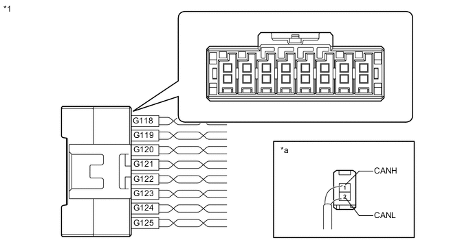
*1 No. 1 CAN Junction Connector - - *a Rear view of wire harness connector
(to No. 1 CAN Junction Connector)
- - No. 1 CAN Junction Connector Wiring Color Connect to G118-1 (CANH) L No. 3 CAN junction connector G118-2 (CANL) W G119-1 (CANH) V No. 2 CAN junction connector G119-2 (CANL) W G120-1 (CANH) R Brake actuator assembly (skid control ECU) G120-2 (CANL) W G121-1 (CANH) LG Power steering ECU assembly G121-2 (CANL) W G122-1 (CANH) P Spiral with sensor cable sub-assembly (steering angle sensor)*1 G122-2 (CANL) W G123-1 (CANH) Y Main body ECU (multiplex network body ECU) G123-2 (CANL) W G124-1 (CANH) B DLC3 G124-2 (CANL) W G125-1 (CANH) G Lane departure warning camera*2 G125-2 (CANL) W *1: w/ Vehicle Stability Control System
*2: w/ Lane Departure Alert System
-
No. 2 CAN Junction Connector
Tech Tips
Connectors that connect to the No. 2 CAN junction connector can be distinguished by the color of their CAN bus wires. When the connectors have been disconnected from the CAN junction connector, reconnecting the connectors to non-original positions on the CAN junction connector does not affect system performance. However, it is preferred to reconnect the connectors to their original positions to avoid negative effects on the wiring such as tension on the wiring harnesses, and to make future maintenance easier.
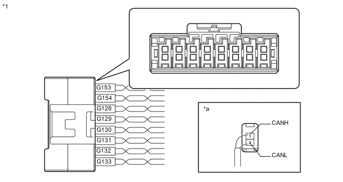
*1 No. 2 CAN Junction Connector - - *a Rear view of wire harness connector
(to No. 2 CAN Junction Connector)
- - No. 2 CAN Junction Connector Wiring Color Connect to G128-1 (CANH) G Combination meter assembly G128-2 (CANL) W G129-1 (CANH) V No. 1 CAN junction connector G129-2 (CANL) W G130-1 (CANH) Y
-
Radio and display receiver assembly*1
-
Navigation receiver assembly*2
-
Navigation ECU sub-assembly*3
G130-2 (CANL) W G131-1 (CANH) L 4WD ECU assembly*4 G131-2 (CANL) W G132-1 (CANH) R Certification ECU (smart key ECU assembly)*5 G132-2 (CANL) W G133-1 (CANH) BR Airbag sensor assembly G133-2 (CANL) W G153-1 (CANH) B Air conditioning amplifier assembly G153-2 (CANL) W G154-1 (CANH) LG Engine stop and start ECU*6 G154-2 (CANL) W *1: w/ Audio and Visual System (for Radio and Display Type)
*2: w/ Navigation System (for SD)
*3: w/ Navigation System (for HDD)
*4: for 4WD/AWD
*5: w/ Entry and Start System
*6: w/ Stop and Start System
-
-
No. 3 CAN Junction Connector
Tech Tips
Connectors that connect to the No. 3 CAN junction connector can be distinguished by the color of their CAN bus wires. When the connectors have been disconnected from the CAN junction connector, reconnecting the connectors to non-original positions on the CAN junction connector does not affect system performance. However, it is preferred to reconnect the connectors to their original positions to avoid negative effects on the wiring such as tension on the wiring harnesses, and to make future maintenance easier.
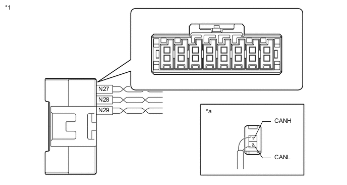
*1 No. 3 CAN Junction Connector - - *a Rear view of wire harness connector
(to No. 3 CAN Junction Connector)
- - No. 3 CAN Junction Connector Wiring Color Connect to N27-1 (CANH) Y ECM N27-2 (CANL) W N28-1 (CANH) L No. 1 CAN junction connector N28-2 (CANL) W N29-1 (CANH) R Blind spot monitor sensor LH* N29-2 (CANL) W *: w/ Blind Spot Monitor System
-
No. 4 CAN Junction Connector (for Power Seat)
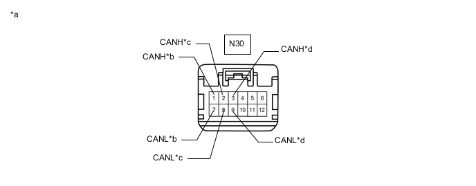
*a Front view of wire harness connector
(to No. 4 CAN Junction Connector)
*b for Main Body ECU (Multiplex Network Body ECU) *c for No. 5 CAN Junction Connector *d for Position Control ECU and Switch Assembly (w/ Seat Memory) No. 4 CAN Junction Connector Wiring Color Connect to N30-1 (CANH) B Main body ECU (multiplex network body ECU) N30-7 (CANL) W N30-2 (CANH) V No. 5 CAN junction connector N30-8 (CANL) W N30-3 (CANH) R Position control ECU and switch assembly* N30-9 (CANL) W *: w/ Seat Memory
-
No. 5 CAN Junction Connector (w/ Power Back Door System)
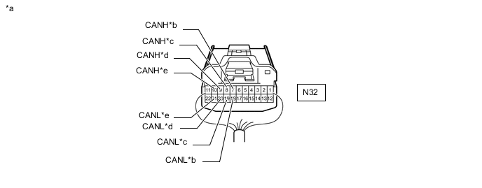
*a Rear view of wire harness connector
(to No. 5 Junction Connector)
*b for Television Camera Assembly (w/ Parking Assist Monitor System [for Camera built-in ECU]) *c for Multiplex Network Door ECU *d for No. 1 CAN Junction Terminal *e
-
for No. 4 CAN Junction Connector (for Power Seat)
-
for Main Body ECU (Multiplex Network Body ECU) (except Power Seat)
- - No. 5 CAN Junction Connector Wiring Color Connect to N32-7 (CANH) P Television camera assembly*1 N32-18 (CANL) W N32-8 (CANH) G Multiplex network door ECU N32-19 (CANL) W N32-9 (CANH) L No. 1 CAN junction terminal N32-20 (CANL) W N32-10 (CANH) V*2, B*3
-
No. 4 CAN junction connector*2
-
Main body ECU (multiplex network body ECU)*3
N32-21 (CANL) W *1: w/ Parking Assist Monitor System (for Camera built-in ECU)
*2: for Power Seat
*3: except Power Seat
-
-
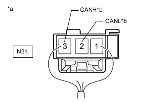
*a Rear view of wire harness connector
(to No. 1 CAN Junction Terminal)
*b for No. 5 CAN Junction Connector No. 1 CAN Junction Terminal (w/ Power Back Door System)
No. 1 CAN Junction Terminal Wiring Color Connect to N31-2 (CANL) W No. 5 CAN junction connector N31-3 (CANH) L
-
-
CHECK DLC3
-
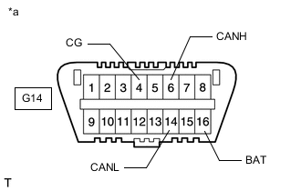
*a Front view of DLC3 Disconnect the cable from the negative (-) battery terminal before measuring the resistances of the CAN main wire and the CAN branch wire.
CAUTION:
Wait at least 90 seconds after disconnecting the cable from the negative (-) battery terminal to disable the SRS system.
Note
-
After turning the cable disconnected from negative (-) battery terminal, waiting time may be required before disconnecting the cable from the battery terminal. Therefore, make sure to read the disconnecting the cable from the battery terminal notice before proceeding with work.
-
When disconnecting the cable, some systems need to be initialized after the cable is reconnected.
-
-
Measure the resistance according to the value(s) in the table below.
Terminal No. (Symbol) Wiring Color Terminal Description Condition Specified Condition G14-6 (CANH) - G14-14 (CANL) B - W HIGH-level CAN bus wire - LOW-level CAN bus wire Cable disconnected from negative (-) battery terminal 54 to 69 Ω G14-6 (CANH) - G14-4 (CG) B - BR HIGH-level CAN bus wire - GND Cable disconnected from negative (-) battery terminal 200 Ω or higher G14-14 (CANL) - G14-4 (CG) W - BR LOW-level CAN bus wire - GND Cable disconnected from negative (-) battery terminal 200 Ω or higher G14-6 (CANH) - G14-16 (BAT) B - L HIGH-level CAN bus wire - Battery positive (+) Cable disconnected from negative (-) battery terminal 6 kΩ or higher G14-14 (CANL) - G14-16 (BAT) W - L LOW-level CAN bus wire - Battery positive (+) Cable disconnected from negative (-) battery terminal 6 kΩ or higher
-
-
CHECK ECM
-
for 2AR-FE:
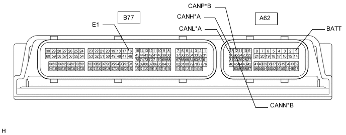
*A V Bus *B Local Bus
-
Disconnect the ECM connectors.
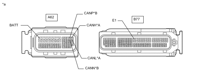
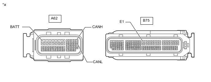
*A V Bus *B Local Bus *a Front view of wire harness connector
(to ECM)
- - -
Measure the resistance according to the value(s) in the table below.
V Bus Terminal No. (Symbol) Wiring Color Terminal Description Condition Specified Condition A62-13 (CANH) - A62-26 (CANL) Y - W HIGH-level CAN bus wire - LOW-level CAN bus wire Cable disconnected from negative (-) battery terminal 108 to 132 Ω A62-13 (CANH) - B77-16 (E1) Y - BR HIGH-level CAN bus wire - GND Cable disconnected from negative (-) battery terminal 200 Ω or higher A62-26 (CANL) - B77-16 (E1) W - BR LOW-level CAN bus wire - GND Cable disconnected from negative (-) battery terminal 200 Ω or higher A62-13 (CANH) - A62-1 (BATT) Y - W HIGH-level CAN bus wire - Battery positive (+) Cable disconnected from negative (-) battery terminal 6 kΩ or higher A62-26 (CANL) - A62-1 (BATT) W - W LOW-level CAN bus wire - Battery positive (+) Cable disconnected from negative (-) battery terminal 6 kΩ or higher Local Bus Terminal No. (Symbol) Wiring Color Terminal Description Condition Specified Condition A62-12 (CANP) - A62-25 (CANN) B - W HIGH-level CAN bus wire - LOW-level CAN bus wire Cable disconnected from negative (-) battery terminal 108 to 132 Ω A62-12 (CANP) - B77-16 (E1) B - BR HIGH-level CAN bus wire - GND Cable disconnected from negative (-) battery terminal 200 Ω or higher A62-25 (CANN) - B77-16 (E1) W - BR LOW-level CAN bus wire - GND Cable disconnected from negative (-) battery terminal 200 Ω or higher A62-12 (CANP) - A62-1 (BATT) B - W HIGH-level CAN bus wire - Battery positive (+) Cable disconnected from negative (-) battery terminal 6 kΩ or higher A62-25 (CANN) - A62-1 (BATT) W - W LOW-level CAN bus wire - Battery positive (+) Cable disconnected from negative (-) battery terminal 6 kΩ or higher
-
-
for 3ZR-FAE:
*A V Bus *B Sub Bus 15
-
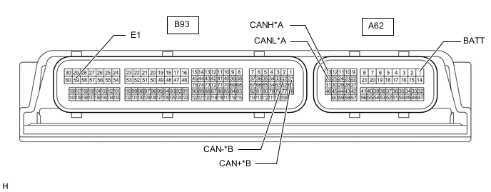
Disconnect the ECM connectors.
*A V Bus *B Sub Bus 15 *a Front view of wire harness connector
(to ECM)
- - -
Measure the resistance according to the value(s) in the table below.
V Bus Terminal No. (Symbol) Wiring Color Terminal Description Condition Specified Condition A62-13 (CANH) - A62-26 (CANL) Y - W HIGH-level CAN bus wire - LOW-level CAN bus wire Cable disconnected from negative (-) battery terminal 108 to 132 Ω A62-13 (CANH) - B93-59 (E1) Y - BR HIGH-level CAN bus wire - GND Cable disconnected from negative (-) battery terminal 200 Ω or higher A62-26 (CANL) - B93-59 (E1) W - BR LOW-level CAN bus wire - GND Cable disconnected from negative (-) battery terminal 200 Ω or higher A62-13 (CANH) - A62-1 (BATT) Y - W HIGH-level CAN bus wire - Battery positive (+) Cable disconnected from negative (-) battery terminal 6 kΩ or higher A62-26 (CANL) - A62-1 (BATT) W - W LOW-level CAN bus wire - Battery positive (+) Cable disconnected from negative (-) battery terminal 6 kΩ or higher Sub Bus 15 Terminal No. (Symbol) Wiring Color Terminal Description Condition Specified Condition B93-31 (CAN+) - B93-32 (CAN-) Y - L HIGH-level CAN bus wire - LOW-level CAN bus wire Cable disconnected from negative (-) battery terminal 108 to 132 Ω B93-31 (CAN+) - B93-59 (E1) Y - BR HIGH-level CAN bus wire - GND Cable disconnected from negative (-) battery terminal 200 Ω or higher B93-32 (CAN-) - B93-59 (E1) L - BR LOW-level CAN bus wire - GND Cable disconnected from negative (-) battery terminal 200 Ω or higher B93-31 (CAN+) - A62-1 (BATT) Y - W HIGH-level CAN bus wire - Battery positive (+) Cable disconnected from negative (-) battery terminal 6 kΩ or higher B93-32 (CAN-) - A62-1 (BATT) L - W LOW-level CAN bus wire - Battery positive (+) Cable disconnected from negative (-) battery terminal 6 kΩ or higher
-
-
for 3ZR-FE:
-
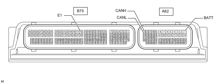
Disconnect the ECM connectors.
*a Front view of wire harness connector
(to ECM)
- - -
Measure the resistance according to the value(s) in the table below.
Terminal No. (Symbol) Wiring Color Terminal Description Condition Specified Condition A62-13 (CANH) - A62-26 (CANL) Y - W HIGH-level CAN bus wire - LOW-level CAN bus wire Cable disconnected from negative (-) battery terminal 108 to 132 Ω A62-13 (CANH) - B75-16 (E1) Y - BR HIGH-level CAN bus wire - GND Cable disconnected from negative (-) battery terminal 200 Ω or higher A62-26 (CANL) - B75-16 (E1) W - BR LOW-level CAN bus wire - GND Cable disconnected from negative (-) battery terminal 200 Ω or higher A62-13 (CANH) - A62-1 (BATT) Y - W HIGH-level CAN bus wire - Battery positive (+) Cable disconnected from negative (-) battery terminal 6 kΩ or higher A62-26 (CANL) - A62-1 (BATT) W - W LOW-level CAN bus wire - Battery positive (+) Cable disconnected from negative (-) battery terminal 6 kΩ or higher
-
-
for 1AD-FTV, 2AD-FHV, 2AD-CCo, 2AD-DPF:
*A V Bus *B Sub Bus 15 *C Local Bus - -
-
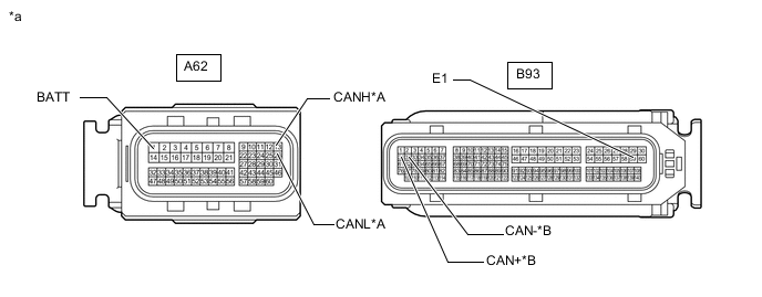
Disconnect the ECM connectors.
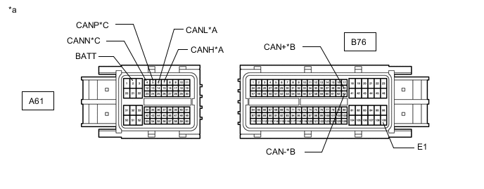
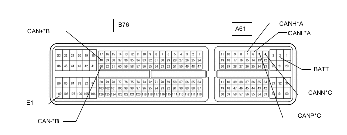
*A V Bus *B Sub Bus 15 *C Local Bus - - *a Front view of wire harness connector
(to ECM)
- - -
Measure the resistance according to the value(s) in the table below.
V Bus Terminal No. (Symbol) Wiring Color Terminal Description Condition Specified Condition A61-7 (CANH) - A61-6 (CANL) Y - W HIGH-level CAN bus wire - LOW-level CAN bus wire Cable disconnected from negative (-) battery terminal 108 to 132 Ω A61-7 (CANH) - B76-109 (E1) Y - BR HIGH-level CAN bus wire - GND Cable disconnected from negative (-) battery terminal 200 Ω or higher A61-6 (CANL) - B76-109 (E1) W - BR LOW-level CAN bus wire - GND Cable disconnected from negative (-) battery terminal 200 Ω or higher A61-7 (CANH) - A61-2 (BATT) Y - W HIGH-level CAN bus wire - Battery positive (+) Cable disconnected from negative (-) battery terminal 6 kΩ or higher A61-6 (CANL) - A61-2 (BATT) W - W LOW-level CAN bus wire - Battery positive (+) Cable disconnected from negative (-) battery terminal 6 kΩ or higher Sub Bus 15 Terminal No. (Symbol) Wiring Color Terminal Description Condition Specified Condition B76-40 (CAN+) - B76-63 (CAN-) Y - B HIGH-level CAN bus wire - LOW-level CAN bus wire Cable disconnected from negative (-) battery terminal 108 to 132 Ω B76-40 (CAN+) - B76-109 (E1) Y - BR HIGH-level CAN bus wire - GND Cable disconnected from negative (-) battery terminal 200 Ω or higher B76-63 (CAN-) - B76-109 (E1) B - BR LOW-level CAN bus wire - GND Cable disconnected from negative (-) battery terminal 200 Ω or higher B76-40 (CAN+) - A61-2 (BATT) Y - W HIGH-level CAN bus wire - Battery positive (+) Cable disconnected from negative (-) battery terminal 6 kΩ or higher B76-63 (CAN-) - A61-2 (BATT) B - W LOW-level CAN bus wire - Battery positive (+) Cable disconnected from negative (-) battery terminal 6 kΩ or higher Local Bus Terminal No. (Symbol) Wiring Color Terminal Description Condition Specified Condition A61-5 (CANP) - A61-4 (CANN) B - W HIGH-level CAN bus wire - LOW-level CAN bus wire Cable disconnected from negative (-) battery terminal 108 to 132 Ω A61-5 (CANP) - B76-109 (E1) B - BR HIGH-level CAN bus wire - GND Cable disconnected from negative (-) battery terminal 200 Ω or higher A61-4 (CANN) - B76-109 (E1) W - BR LOW-level CAN bus wire - GND Cable disconnected from negative (-) battery terminal 200 Ω or higher A61-5 (CANP) - A61-2 (BATT) B - W HIGH-level CAN bus wire - Battery positive (+) Cable disconnected from negative (-) battery terminal 6 kΩ or higher A61-4 (CANN) - A61-2 (BATT) W - W LOW-level CAN bus wire - Battery positive (+) Cable disconnected from negative (-) battery terminal 6 kΩ or higher
-
-
-
CHECK MAIN BODY ECU (MULTIPLEX NETWORK BODY ECU) AND INSTRUMENT PANEL JUNCTION BLOCK ASSEMBLY
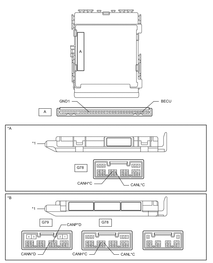
*A Main Body ECU (Multiplex Network Body ECU) with 1 Connector *B Main Body ECU (Multiplex Network Body ECU) with 3 Connectors *C V Bus *D Sub Bus 1 *1 Main Body ECU (Multiplex Network Body ECU) - -
-
Remove the main body ECU (multiplex network body ECU).
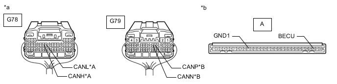
*A V Bus *B Sub Bus 1 *a Rear view of wire harness connector
(to Main Body ECU [Multiplex Network Body ECU])
*b Front view of wire harness connector
(to Main Body ECU [Multiplex Network Body ECU])
-
Reconnect the instrument panel junction block assembly connectors.
-
Measure the resistance according to the value(s) in the table below.
V Bus Terminal No. (Symbol) Wiring Color Terminal Description Condition Specified Condition G78-14 (CANH) - G78-13 (CANL) Y - W HIGH-level CAN bus wire - LOW-level CAN bus wire Cable disconnected from negative (-) battery terminal 54 to 69 Ω G78-14 (CANH) - A-11 (GND1) Y - None HIGH-level CAN bus wire - GND Cable disconnected from negative (-) battery terminal 200 Ω or higher G78-13 (CANL) - A-11 (GND1) W - None LOW-level CAN bus wire - GND Cable disconnected from negative (-) battery terminal 200 Ω or higher G78-14 (CANH) - A-30 (BECU) Y - None HIGH-level CAN bus wire - Battery positive (+) Cable disconnected from negative (-) battery terminal 6 kΩ or higher G78-13 (CANL) - A-30 (BECU) W - None LOW-level CAN bus wire - Battery positive (+) Cable disconnected from negative (-) battery terminal 6 kΩ or higher Sub Bus 1 Terminal No. (Symbol) Wiring Color Terminal Description Condition Specified Condition G79-9 (CANP) - G79-10 (CANN) B - W HIGH-level CAN bus wire - LOW-level CAN bus wire Cable disconnected from negative (-) battery terminal 108 to 132 Ω G79-9 (CANP) - A-11 (GND1) B - None HIGH-level CAN bus wire - GND Cable disconnected from negative (-) battery terminal 200 Ω or higher G79-10 (CANN) - A-11 (GND1) W - None LOW-level CAN bus wire - GND Cable disconnected from negative (-) battery terminal 200 Ω or higher G79-9 (CANP) - A-30 (BECU) B - None HIGH-level CAN bus wire - Battery positive (+) Cable disconnected from negative (-) battery terminal 6 kΩ or higher G79-10 (CANN) - A-30 (BECU) W - None LOW-level CAN bus wire - Battery positive (+) Cable disconnected from negative (-) battery terminal 6 kΩ or higher
-
-
CHECK COMBINATION METER ASSEMBLY

-
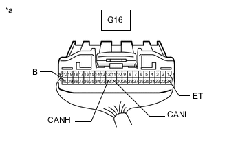
*a Rear view of wire harness connector
(to Combination Meter Assembly)
Disconnect the combination meter assembly connector.
-
Measure the resistance according to the value(s) in the table below.
Terminal No. (Symbol) Wiring Color Terminal Description Condition Specified Condition G16-32 (CANH) - G16-31 (CANL) G - W HIGH-level CAN bus wire - LOW-level CAN bus wire Cable disconnected from negative (-) battery terminal 108 to 132 Ω G16-32 (CANH) - G16-21 (ET) G - BR HIGH-level CAN bus wire - GND Cable disconnected from negative (-) battery terminal 200 Ω or higher G16-31 (CANL) - G16-21 (ET) W - BR LOW-level CAN bus wire - GND Cable disconnected from negative (-) battery terminal 200 Ω or higher G16-32 (CANH) - G16-40 (B) G - Y HIGH-level CAN bus wire - Battery positive (+) Cable disconnected from negative (-) battery terminal 6 kΩ or higher G16-31 (CANL) - G16-40 (B) W - Y LOW-level CAN bus wire - Battery positive (+) Cable disconnected from negative (-) battery terminal 6 kΩ or higher
-
-
CHECK AIRBAG SENSOR ASSEMBLY
-
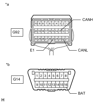
*a Rear view of wire harness connector
(to Airbag Sensor Assembly)
*b Front view of DLC3 Disconnect the airbag sensor assembly connector.
-
Measure the resistance according to the value(s) in the table below.
Terminal No. (Symbol) Wiring Color Terminal Description Condition Specified Condition G92-13 (CANH) - G92-22 (CANL) BR - W HIGH-level CAN bus wire - LOW-level CAN bus wire Cable disconnected from negative (-) battery terminal 54 to 69 Ω G92-13 (CANH) - G92-25 (E1) BR - W-B HIGH-level CAN bus wire - GND Cable disconnected from negative (-) battery terminal 200 Ω or higher G92-22 (CANL) - G92-25 (E1) W - W-B LOW-level CAN bus wire - GND Cable disconnected from negative (-) battery terminal 200 Ω or higher G92-13 (CANH) - G14-16 (BAT) BR - L HIGH-level CAN bus wire - Battery positive (+) Cable disconnected from negative (-) battery terminal 6 kΩ or higher G92-22 (CANL) - G14-16 (BAT) W - L LOW-level CAN bus wire - Battery positive (+) Cable disconnected from negative (-) battery terminal 6 kΩ or higher
-
-
CHECK BRAKE ACTUATOR ASSEMBLY (SKID CONTROL ECU)
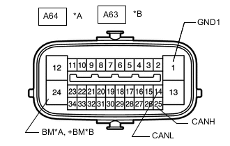
*A w/ Vehicle Stability Control System *B w/o Vehicle Stability Control System
-
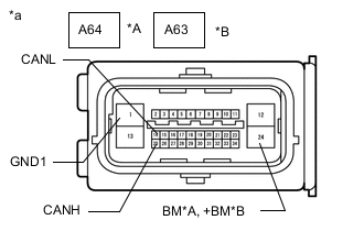
*A w/ Vehicle Stability Control System *B w/o Vehicle Stability Control System *a Front view of wire harness connector
(to Brake Actuator Assembly [Skid Control ECU])
Disconnect the brake actuator assembly (skid control ECU) connector.
-
Measure the resistance according to the value(s) in the table below.
w/ Vehicle Stability Control System Terminal No. (Symbol) Wiring Color Terminal Description Condition Specified Condition A64-25 (CANH) - A64-14 (CANL) R - W HIGH-level CAN bus wire - LOW-level CAN bus wire Cable disconnected from negative (-) battery terminal 54 to 69 Ω A64-25 (CANH) - A64-1 (GND1) R - W-B HIGH-level CAN bus wire - GND Cable disconnected from negative (-) battery terminal 200 Ω or higher A64-14 (CANL) - A64-1 (GND1) W - W-B LOW-level CAN bus wire - GND Cable disconnected from negative (-) battery terminal 200 Ω or higher A64-25 (CANH) - A64-24 (BM) R - B HIGH-level CAN bus wire - Battery positive (+) Cable disconnected from negative (-) battery terminal 6 kΩ or higher A64-14 (CANL) - A64-24 (BM) W - B LOW-level CAN bus wire - Battery positive (+) Cable disconnected from negative (-) battery terminal 6 kΩ or higher w/o Vehicle Stability Control System Terminal No. (Symbol) Wiring Color Terminal Description Condition Specified Condition A63-25 (CANH) - A63-14 (CANL) R - W HIGH-level CAN bus wire - LOW-level CAN bus wire Cable disconnected from negative (-) battery terminal 54 to 69 Ω A63-25 (CANH) - A63-1 (GND1) R - W-B HIGH-level CAN bus wire - GND Cable disconnected from negative (-) battery terminal 200 Ω or higher A63-14 (CANL) - A63-1 (GND1) W - W-B LOW-level CAN bus wire - GND Cable disconnected from negative (-) battery terminal 200 Ω or higher A63-25 (CANH) - A63-24 (+BM) R - B HIGH-level CAN bus wire - Battery positive (+) Cable disconnected from negative (-) battery terminal 6 kΩ or higher A63-14 (CANL) - A63-24 (+BM) W - B LOW-level CAN bus wire - Battery positive (+) Cable disconnected from negative (-) battery terminal 6 kΩ or higher
-
-
CHECK SPIRAL WITH SENSOR CABLE SUB-ASSEMBLY (STEERING ANGLE SENSOR) (w/ Vehicle Stability Control System)
-
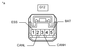
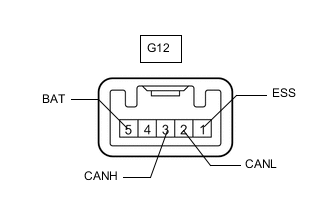
*a Front view of wire harness connector
(to Spiral with Sensor Cable Sub-assembly [Steering Angle Sensor])
Disconnect the spiral with sensor cable sub-assembly (steering angle sensor) connector.
-
Measure the resistance according to the value(s) in the table below.
Terminal No. (Symbol) Wiring Color Terminal Description Condition Specified Condition G12-3 (CANH) - G12-2 (CANL) P - W HIGH-level CAN bus wire - LOW-level CAN bus wire Cable disconnected from negative (-) battery terminal 54 to 69 Ω G12-3 (CANH) - G12-1 (ESS) P - BR HIGH-level CAN bus wire - GND Cable disconnected from negative (-) battery terminal 200 Ω or higher G12-2 (CANL) - G12-1 (ESS) W - BR LOW-level CAN bus wire - GND Cable disconnected from negative (-) battery terminal 200 Ω or higher G12-3 (CANH) - G12-5 (BAT) P - SB HIGH-level CAN bus wire - Battery positive (+) Cable disconnected from negative (-) battery terminal 6 kΩ or higher G12-2 (CANL) - G12-5 (BAT) W - SB LOW-level CAN bus wire - Battery positive (+) Cable disconnected from negative (-) battery terminal 6 kΩ or higher
-
-
CHECK CERTIFICATION ECU (SMART KEY ECU ASSEMBLY) (w/ Entry and Start System)
-
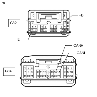
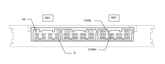
*a Front view of wire harness connector
(to Certification ECU [Smart Key ECU Assembly])
Disconnect the certification ECU (smart key ECU assembly) connectors.
-
Measure the resistance according to the value(s) in the table below.
Terminal No. (Symbol) Wiring Color Terminal Description Condition Specified Condition G84-14 (CANH) - G84-15 (CANL) R - W HIGH-level CAN bus wire - LOW-level CAN bus wire Cable disconnected from negative (-) battery terminal 54 to 69 Ω G84-14 (CANH) - G82-11 (E) R - BR HIGH-level CAN bus wire - GND Cable disconnected from negative (-) battery terminal 200 Ω or higher G84-15 (CANL) - G82-11 (E) W - BR LOW-level CAN bus wire - GND Cable disconnected from negative (-) battery terminal 200 Ω or higher G84-14 (CANH) - G82-2 (+B) R - W HIGH-level CAN bus wire - Battery positive (+) Cable disconnected from negative (-) battery terminal 6 kΩ or higher G84-15 (CANL) - G82-2 (+B) W - W LOW-level CAN bus wire - Battery positive (+) Cable disconnected from negative (-) battery terminal 6 kΩ or higher
-
-
CHECK RADIO AND DISPLAY RECEIVER ASSEMBLY (w/ Audio and Visual System [for Radio and Display Type])

-
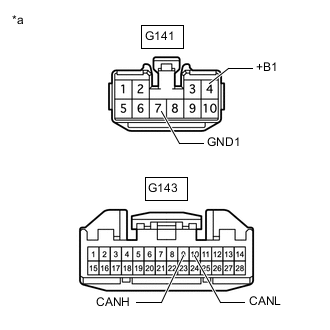
*a Front view of wire harness connector
(to Radio and Display Receiver Assembly)
Disconnect the radio and display receiver assembly connectors.
-
Measure the resistance according to the value(s) in the table below.
Terminal No. (Symbol) Wiring Color Terminal Description Condition Specified Condition G143-9 (CANH) - G143-10 (CANL) Y - W HIGH-level CAN bus wire - LOW-level CAN bus wire Cable disconnected from negative (-) battery terminal 54 to 69 Ω G143-9 (CANH) - G141-7 (GND1) Y - BR HIGH-level CAN bus wire - GND Cable disconnected from negative (-) battery terminal 200 Ω or higher G143-10 (CANL) - G141-7 (GND1) W - BR LOW-level CAN bus wire - GND Cable disconnected from negative (-) battery terminal 200 Ω or higher G143-9 (CANH) - G141-4 (+B1) Y - SB HIGH-level CAN bus wire - Battery positive (+) Cable disconnected from negative (-) battery terminal 6 kΩ or higher G143-10 (CANL) - G141-4 (+B1) W - SB LOW-level CAN bus wire - Battery positive (+) Cable disconnected from negative (-) battery terminal 6 kΩ or higher
-
-
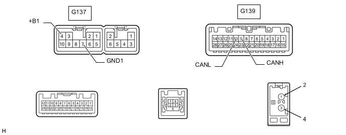
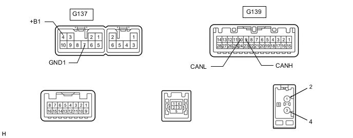
CHECK NAVIGATION RECEIVER ASSEMBLY (w/ Navigation System [for SD])
-
*a Front view of wire harness connector
(to Navigation Receiver assembly)
Disconnect the navigation receiver assembly connectors.
-
Measure the resistance according to the value(s) in the table below.
Terminal No. (Symbol) Wiring Color Terminal Description Condition Specified Condition G139-9 (CANH) - G139-10 (CANL) Y - W HIGH-level CAN bus wire - LOW-level CAN bus wire Cable disconnected from negative (-) battery terminal 54 to 69 Ω G139-9 (CANH) - G137-7 (GND1) Y - BR HIGH-level CAN bus wire - GND Cable disconnected from negative (-) battery terminal 200 Ω or higher G139-10 (CANL) - G137-7 (GND1) W - BR LOW-level CAN bus wire - GND Cable disconnected from negative (-) battery terminal 200 Ω or higher G139-9 (CANH) - G137-4 (+B1) Y - SB HIGH-level CAN bus wire - Battery positive (+) Cable disconnected from negative (-) battery terminal 6 kΩ or higher G139-10 (CANL) - G137-4 (+B1) W - SB LOW-level CAN bus wire - Battery positive (+) Cable disconnected from negative (-) battery terminal 6 kΩ or higher
-
-
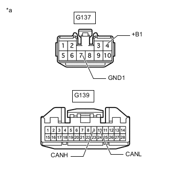
CHECK NAVIGATION ECU SUB-ASSEMBLY (w/ Navigation System [for HDD])
-
*a Front view of wire harness connector
(to Navigation ECU Sub-assembly)
Disconnect the navigation ECU sub-assembly connectors.
-
Measure the resistance according to the value(s) in the table below.
Terminal No. (Symbol) Wiring Color Terminal Description Condition Specified Condition G139-9 (CANH) - G139-10 (CANL) Y - W HIGH-level CAN bus wire - LOW-level CAN bus wire Cable disconnected from negative (-) battery terminal 54 to 69 Ω G139-9 (CANH) - G137-7 (GND1) Y - BR HIGH-level CAN bus wire - GND Cable disconnected from negative (-) battery terminal 200 Ω or higher G139-10 (CANL) - G137-7 (GND1) W - BR LOW-level CAN bus wire - GND Cable disconnected from negative (-) battery terminal 200 Ω or higher G139-9 (CANH) - G137-4 (+B1) Y - SB HIGH-level CAN bus wire - Battery positive (+) Cable disconnected from negative (-) battery terminal 6 kΩ or higher G139-10 (CANL) - G137-4 (+B1) W - SB LOW-level CAN bus wire - Battery positive (+) Cable disconnected from negative (-) battery terminal 6 kΩ or higher
-
-
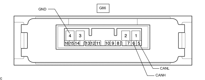
CHECK 4WD ECU ASSEMBLY (for 4WD/AWD)
-
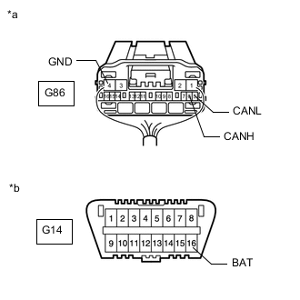
*a Rear view of wire harness connector
(to 4WD ECU Assembly)
*b Front view of DLC3 Disconnect the 4WD ECU assembly connector.
-
Measure the resistance according to the value(s) in the table below.
Terminal No. (Symbol) Wiring Color Terminal Description Condition Specified Condition G86-6 (CANH) - G86-5 (CANL) L - W HIGH-level CAN bus wire - LOW-level CAN bus wire Cable disconnected from negative (-) battery terminal 54 to 69 Ω G86-6 (CANH) - G86-4 (GND) L - W-B HIGH-level CAN bus wire - GND Cable disconnected from negative (-) battery terminal 200 Ω or higher G86-5 (CANL) - G86-4 (GND) W - W-B LOW-level CAN bus wire - GND Cable disconnected from negative (-) battery terminal 200 Ω or higher G86-6 (CANH) - G14-16 (BAT) L - L HIGH-level CAN bus wire - Battery positive (+) Cable disconnected from negative (-) battery terminal 6 kΩ or higher G86-5 (CANL) - G14-16 (BAT) W - L LOW-level CAN bus wire - Battery positive (+) Cable disconnected from negative (-) battery terminal 6 kΩ or higher
-
-
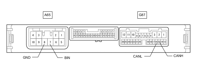
CHECK ENGINE STOP AND START ECU (w/ Stop and Start System)
-
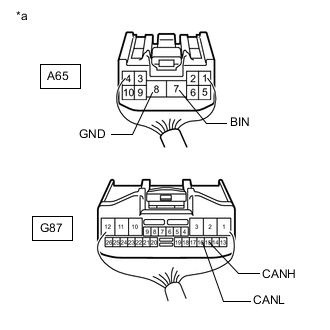
*a Rear view of wire harness connector
(to Engine Stop and Start ECU)
Disconnect the engine stop and start ECU connectors.
-
Measure the resistance according to the value(s) in the table below.
Terminal No. (Symbol) Wiring Color Terminal Description Condition Specified Condition G87-15 (CANH) - G87-16 (CANL) LG - W HIGH-level CAN bus wire - LOW-level CAN bus wire Cable disconnected from negative (-) battery terminal 54 to 69 Ω G87-15 (CANH) - A65-8 (GND) LG - W-B HIGH-level CAN bus wire - GND Cable disconnected from negative (-) battery terminal 200 Ω or higher G87-16 (CANL) - A65-8 (GND) W - W-B LOW-level CAN bus wire - GND Cable disconnected from negative (-) battery terminal 200 Ω or higher G87-15 (CANH) - A65-7 (BIN) LG - L HIGH-level CAN bus wire - Battery positive (+) Cable disconnected from negative (-) battery terminal 6 kΩ or higher G87-16 (CANL) - A65-7 (BIN) W - L LOW-level CAN bus wire - Battery positive (+) Cable disconnected from negative (-) battery terminal 6 kΩ or higher
-
-
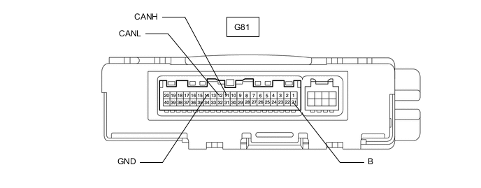
CHECK AIR CONDITIONING AMPLIFIER ASSEMBLY
-
for Automatic Air Conditioning System:
-
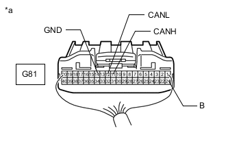
*a Rear view of wire harness connector
(to Air Conditioning Amplifier Assembly)
Disconnect the air conditioning amplifier assembly connector.
-
Measure the resistance according to the value(s) in the table below.
Terminal No. (Symbol) Wiring Color Terminal Description Condition Specified Condition G81-11 (CANH) - G81-12 (CANL) B - W HIGH-level CAN bus wire - LOW-level CAN bus wire Cable disconnected from negative (-) battery terminal 54 to 69 Ω G81-11 (CANH) - G81-14 (GND) B - W-B HIGH-level CAN bus wire - GND Cable disconnected from negative (-) battery terminal 200 Ω or higher G81-12 (CANL) - G81-14 (GND) W - W-B LOW-level CAN bus wire - GND Cable disconnected from negative (-) battery terminal 200 Ω or higher G81-11 (CANH) - G81-21 (B) B - GR HIGH-level CAN bus wire - Battery positive (+) Cable disconnected from negative (-) battery terminal 6 kΩ or higher G81-12 (CANL) - G81-21 (B) W - GR LOW-level CAN bus wire - Battery positive (+) Cable disconnected from negative (-) battery terminal 6 kΩ or higher
-
-
for Manual Air Conditioning System:

-
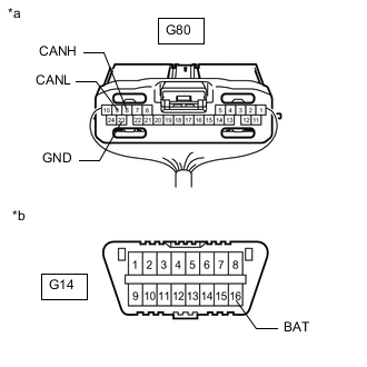
*a Rear view of wire harness connector
(to Air Conditioning Amplifier Assembly)
*b Front view of DLC3 Disconnect the air conditioning amplifier assembly connector.
-
Measure the resistance according to the value(s) in the table below.
Terminal No. (Symbol) Wiring Color Terminal Description Condition Specified Condition G80-8 (CANH) - G80-9 (CANL) B - W HIGH-level CAN bus wire - LOW-level CAN bus wire Cable disconnected from negative (-) battery terminal 54 to 69 Ω G80-8 (CANH) - G80-23 (GND) B - W-B HIGH-level CAN bus wire - GND Cable disconnected from negative (-) battery terminal 200 Ω or higher G80-9 (CANL) - G80-23 (GND) W - W-B LOW-level CAN bus wire - GND Cable disconnected from negative (-) battery terminal 200 Ω or higher G80-8 (CANH) - G14-16 (BAT) B - L HIGH-level CAN bus wire - Battery positive (+) Cable disconnected from negative (-) battery terminal 6 kΩ or higher G80-9 (CANL) - G14-16 (BAT) W - L LOW-level CAN bus wire - Battery positive (+) Cable disconnected from negative (-) battery terminal 6 kΩ or higher
-
-
-
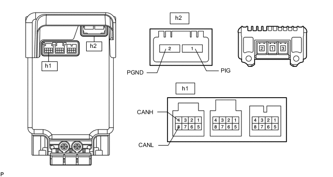
CHECK POWER STEERING ECU ASSEMBLY
-
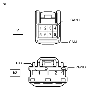
*a Front view of wire harness connector
(to Power Steering ECU Assembly)
Disconnect the power steering ECU assembly connectors.
-
Measure the resistance according to the value(s) in the table below.
Terminal No. (Symbol) Wiring Color Terminal Description Condition Specified Condition h1-4 (CANH) - h1-8 (CANL) W - B HIGH-level CAN bus wire - LOW-level CAN bus wire Cable disconnected from negative (-) battery terminal 54 to 69 Ω h1-4 (CANH) - h2-2 (PGND) W - R HIGH-level CAN bus wire - GND Cable disconnected from negative (-) battery terminal 200 Ω or higher h1-8 (CANL) - h2-2 (PGND) B - R LOW-level CAN bus wire - GND Cable disconnected from negative (-) battery terminal 200 Ω or higher h1-4 (CANH) - h2-1 (PIG) W - R HIGH-level CAN bus wire - Battery positive (+) Cable disconnected from negative (-) battery terminal 6 kΩ or higher h1-8 (CANL) - h2-1 (PIG) B - R LOW-level CAN bus wire - Battery positive (+) Cable disconnected from negative (-) battery terminal 6 kΩ or higher
-
-
CHECK BLIND SPOT MONITOR SENSOR LH (w/ Blind Spot Monitor System)
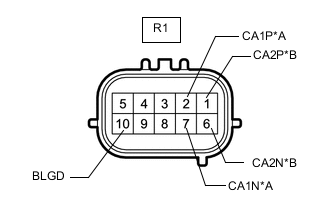
*A V Bus *B Sensor Bus
-
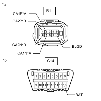
*A V Bus *B Sensor Bus *a Front view of wire harness connector
(to Blind Spot Monitor Sensor LH)
*b Front view of DLC3 Disconnect the blind spot monitor sensor LH connector.
-
Measure the resistance according to the value(s) in the table below.
V Bus Terminal No. (Symbol) Wiring Color Terminal Description Condition Specified Condition R1-2 (CA1P) - R1-7 (CA1N) R - W HIGH-level CAN bus wire - LOW-level CAN bus wire Cable disconnected from negative (-) battery terminal 54 to 69 Ω R1-2 (CA1P) - R1-10 (BLGD) R - W-B HIGH-level CAN bus wire - GND Cable disconnected from negative (-) battery terminal 200 Ω or higher R1-7 (CA1N) - R1-10 (BLGD) W - W-B LOW-level CAN bus wire - GND Cable disconnected from negative (-) battery terminal 200 Ω or higher R1-2 (CA1P) - G14-16 (BAT) R - L HIGH-level CAN bus wire - Battery positive (+) Cable disconnected from negative (-) battery terminal 6 kΩ or higher R1-7 (CA1N) - G14-16 (BAT) W - L LOW-level CAN bus wire - Battery positive (+) Cable disconnected from negative (-) battery terminal 6 kΩ or higher Sensor Bus Terminal No. (Symbol) Wiring Color Terminal Description Condition Specified Condition R1-1 (CA2P) - R1-6 (CA2N) W - B HIGH-level CAN bus wire - LOW-level CAN bus wire Cable disconnected from negative (-) battery terminal 108 to 132 Ω R1-1 (CA2P) - R1-10 (BLGD) W - W-B HIGH-level CAN bus wire - GND Cable disconnected from negative (-) battery terminal 200 Ω or higher R1-6 (CA2N) - R1-10 (BLGD) B - W-B LOW-level CAN bus wire - GND Cable disconnected from negative (-) battery terminal 200 Ω or higher R1-1 (CA2P) - G14-16 (BAT) W - L HIGH-level CAN bus wire - Battery positive (+) Cable disconnected from negative (-) battery terminal 6 kΩ or higher R1-6 (CA2N) - G14-16 (BAT) B - L LOW-level CAN bus wire - Battery positive (+) Cable disconnected from negative (-) battery terminal 6 kΩ or higher
-
-
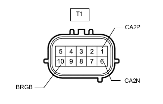
CHECK BLIND SPOT MONITOR SENSOR RH (w/ Blind Spot Monitor System)
-
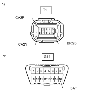
*a Front view of wire harness connector
(to Blind Spot Monitor Sensor RH)
*b Front view of DLC3 Disconnect the blind spot monitor sensor RH connector.
-
Measure the resistance according to the value(s) in the table below.
Terminal No. (Symbol) Wiring Color Terminal Description Condition Specified Condition T1-1 (CA2P) - T1-6 (CA2N) W - B HIGH-level CAN bus wire - LOW-level CAN bus wire Cable disconnected from negative (-) battery terminal 108 to 132 Ω T1-1 (CA2P) - T1-10 (BRGB) W - W-B HIGH-level CAN bus wire - GND Cable disconnected from negative (-) battery terminal 200 Ω or higher T1-6 (CA2N) - T1-10 (BRGB) B - W-B LOW-level CAN bus wire - GND Cable disconnected from negative (-) battery terminal 200 Ω or higher T1-1 (CA2P) - G14-16 (BAT) W - L HIGH-level CAN bus wire - Battery positive (+) Cable disconnected from negative (-) battery terminal 6 kΩ or higher T1-6 (CA2N) - G14-16 (BAT) B - L LOW-level CAN bus wire - Battery positive (+) Cable disconnected from negative (-) battery terminal 6 kΩ or higher
-
-
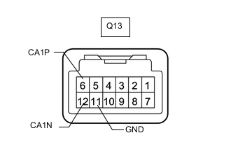
CHECK LANE DEPARTURE WARNING CAMERA (w/ Lane Departure Alert System)
-
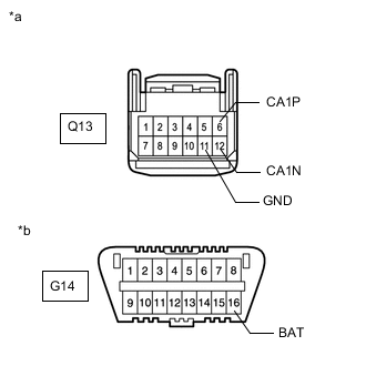
*a Front view of wire harness connector
(to Lane Departure Warning Camera)
*b Front view of DLC3 Disconnect the lane departure warning camera connector.
-
Measure the resistance according to the value(s) in the table below.
Terminal No. (Symbol) Wiring Color Terminal Description Condition Specified Condition Q13-6 (CA1P) - Q13-12 (CA1N) B - W HIGH-level CAN bus wire - LOW-level CAN bus wire Cable disconnected from negative (-) battery terminal 54 to 69 Ω Q13-6 (CA1P) - Q13-11 (GND) B - W-B HIGH-level CAN bus wire - GND Cable disconnected from negative (-) battery terminal 200 Ω or higher Q13-12 (CA1N) - Q13-11 (GND) W - W-B LOW-level CAN bus wire - GND Cable disconnected from negative (-) battery terminal 200 Ω or higher Q13-6 (CA1P) - G14-16 (BAT) B - L HIGH-level CAN bus wire - Battery positive (+) Cable disconnected from negative (-) battery terminal 6 kΩ or higher Q13-12 (CA1N) - G14-16 (BAT) W - L LOW-level CAN bus wire - Battery positive (+) Cable disconnected from negative (-) battery terminal 6 kΩ or higher
-
-
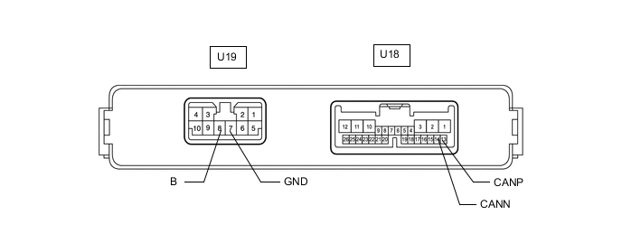
CHECK MULTIPLEX NETWORK DOOR ECU (w/ Power Back Door System)
-
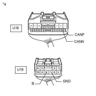
*a Rear view of wire harness connector
(to Multiplex Network Door ECU)
Disconnect the multiplex network door ECU connectors.
-
Measure the resistance according to the value(s) in the table below.
Terminal No. (Symbol) Wiring Color Terminal Description Condition Specified Condition U18-13 (CANP) - U18-14 (CANN) G - W HIGH-level CAN bus wire - LOW-level CAN bus wire Cable disconnected from negative (-) battery terminal 54 to 69 Ω U18-13 (CANP) - U19-7 (GND) G - W-B HIGH-level CAN bus wire - GND Cable disconnected from negative (-) battery terminal 200 Ω or higher U18-14 (CANN) - U19-7 (GND) W - W-B LOW-level CAN bus wire - GND Cable disconnected from negative (-) battery terminal 200 Ω or higher U18-13 (CANP) - U19-8 (B) G - W HIGH-level CAN bus wire - Battery positive (+) Cable disconnected from negative (-) battery terminal 6 kΩ or higher U18-14 (CANN) - U19-8 (B) W - W LOW-level CAN bus wire - Battery positive (+) Cable disconnected from negative (-) battery terminal 6 kΩ or higher
-
-
CHECK POSITION CONTROL ECU AND SWITCH ASSEMBLY (w/ Seat Memory)

-
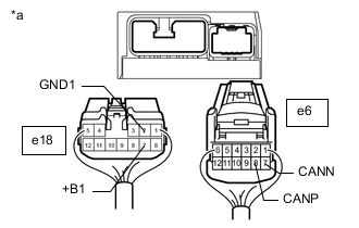
*a Rear view of wire harness connector
(to Position Control ECU and Switch Assembly)
Disconnect the position control ECU assembly connectors.
-
Measure the resistance according to the value(s) in the table below.
Terminal No. (Symbol) Wiring Color Terminal Description Condition Specified Condition e6-8 (CANP) - e6-7 (CANN) L - W HIGH-level CAN bus wire - LOW-level CAN bus wire Cable disconnected from negative (-) battery terminal 54 to 69 Ω e6-8 (CANP) - e18-2 (GND1) L - W-B HIGH-level CAN bus wire - GND Cable disconnected from negative (-) battery terminal 200 Ω or higher e6-7 (CANN) - e18-2 (GND1) W - W-B LOW-level CAN bus wire - GND Cable disconnected from negative (-) battery terminal 200 Ω or higher e6-8 (CANP) - e18-7 (+B1) L - W HIGH-level CAN bus wire - Battery positive (+) Cable disconnected from negative (-) battery terminal 6 kΩ or higher e6-7 (CANN) - e18-7 (+B1) W - W LOW-level CAN bus wire - Battery positive (+) Cable disconnected from negative (-) battery terminal 6 kΩ or higher
-
-
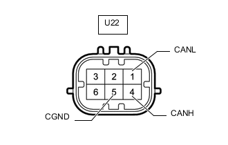
CHECK TELEVISION CAMERA ASSEMBLY (w/ Parking Assist Monitor System [for Camera built-in ECU])
-
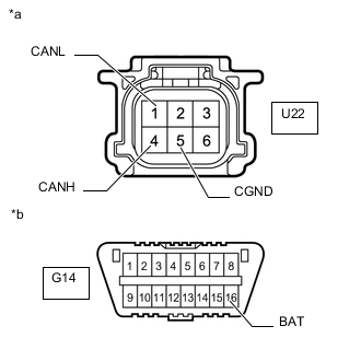
*a Front view of wire harness connector
(to Television Camera Assembly)
*b Front view of DLC3 Disconnect the television camera assembly connector.
-
Measure the resistance according to the value(s) in the table below.
Terminal No. (Symbol) Wiring Color Terminal Description Condition Specified Condition U22-4 (CANH) - U22-1 (CANL) P - W HIGH-level CAN bus wire - LOW-level CAN bus wire Cable disconnected from negative (-) battery terminal 54 to 69 Ω U22-4 (CANH) - U22-5 (CGND) P - BR HIGH-level CAN bus wire - GND Cable disconnected from negative (-) battery terminal 200 Ω or higher U22-1 (CANL) - U22-5 (CGND) W - BR LOW-level CAN bus wire - GND Cable disconnected from negative (-) battery terminal 200 Ω or higher U22-4 (CANH) - G14-16 (BAT) P - L HIGH-level CAN bus wire - Battery positive (+) Cable disconnected from negative (-) battery terminal 6 kΩ or higher U22-1 (CANL) - G14-16 (BAT) W - L LOW-level CAN bus wire - Battery positive (+) Cable disconnected from negative (-) battery terminal 6 kΩ or higher
-
-
CHECK TRANSMISSION CONTROL ECU ASSEMBLY (for 2AD-FHV, 2AD-CCo and Automatic Transaxle)
-
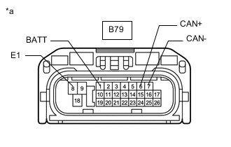
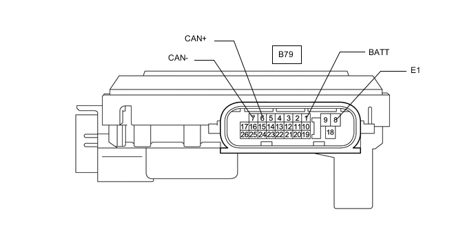
*a Front view of wire harness connector
(to Transmission Control ECU Assembly)
Disconnect the transmission control ECU assembly connector.
-
Measure the resistance according to the value(s) in the table below.
Terminal No. (Symbol) Wiring Color Terminal Description Condition Specified Condition B79-6 (CAN+) - B79-7 (CAN-) Y - B HIGH-level CAN bus wire - LOW-level CAN bus wire Cable disconnected from negative (-) battery terminal 108 to 132 Ω B79-6 (CAN+) - B79-8 (E1) Y - BR HIGH-level CAN bus wire - GND Cable disconnected from negative (-) battery terminal 200 Ω or higher B79-7 (CAN-) - B79-8 (E1) B - BR LOW-level CAN bus wire - GND Cable disconnected from negative (-) battery terminal 200 Ω or higher B79-6 (CAN+) - B79-1 (BATT) Y - W HIGH-level CAN bus wire - Battery positive (+) Cable disconnected from negative (-) battery terminal 6 kΩ or higher B79-7 (CAN-) - B79-1 (BATT) B - W LOW-level CAN bus wire - Battery positive (+) Cable disconnected from negative (-) battery terminal 6 kΩ or higher
-
-
CHECK CONTINUOUSLY VARIABLE VALVE LIFT CONTROLLER ASSEMBLY (for 3ZR-FAE)
-
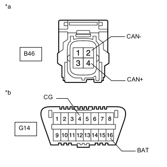
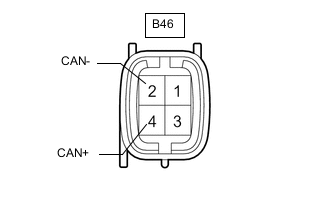
*a Front view of wire harness connector
(to Continuously Variable Valve Lift Controller Assembly)
*b Front view of DLC3 Disconnect the continuously variable valve lift controller assembly connector.
-
Measure the resistance according to the value(s) in the table below.
Terminal No. (Symbol) Wiring Color Terminal Description Condition Specified Condition B46-4 (CAN+) - B46-2 (CAN-) Y - L HIGH-level CAN bus wire - LOW-level CAN bus wire Cable disconnected from negative (-) battery terminal 108 to 132 Ω B46-4 (CAN+) - G14-4 (CG) Y - BR HIGH-level CAN bus wire - GND Cable disconnected from negative (-) battery terminal 200 Ω or higher B46-2 (CAN-) - G14-4 (CG) L - BR LOW-level CAN bus wire - GND Cable disconnected from negative (-) battery terminal 200 Ω or higher B46-4 (CAN+) - G14-16 (BAT) Y - L HIGH-level CAN bus wire - Battery positive (+) Cable disconnected from negative (-) battery terminal 6 kΩ or higher B46-2 (CAN-) - G14-16 (BAT) L - L LOW-level CAN bus wire - Battery positive (+) Cable disconnected from negative (-) battery terminal 6 kΩ or higher
-
-
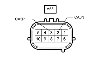
CHECK BATTERY CURRENT SENSOR ASSEMBLY (for 1AD-FTV or w/ Occupant Classification System)
-
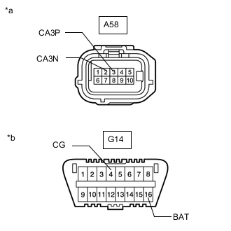
*a Front view of wire harness connector
(to Battery Current Sensor Assembly)
*b Front view of DLC3 Disconnect the battery current sensor assembly connector.
-
Measure the resistance according to the value(s) in the table below.
Terminal No. (Symbol) Wiring Color Terminal Description Condition Specified Condition A58-3 (CA3P) - A58-2 (CA3N) B - W HIGH-level CAN bus wire - LOW-level CAN bus wire Cable disconnected from negative (-) battery terminal 108 to 132 Ω A58-3 (CA3P) - G14-4 (CG) B - BR HIGH-level CAN bus wire - GND Cable disconnected from negative (-) battery terminal 200 Ω or higher A58-2 (CA3N) - G14-4 (CG) W - BR LOW-level CAN bus wire - GND Cable disconnected from negative (-) battery terminal 200 Ω or higher A58-3 (CA3P) - G14-16 (BAT) B - L HIGH-level CAN bus wire - Battery positive (+) Cable disconnected from negative (-) battery terminal 6 kΩ or higher A58-2 (CA3N) - G14-16 (BAT) W - L LOW-level CAN bus wire - Battery positive (+) Cable disconnected from negative (-) battery terminal 6 kΩ or higher
-