LIN COMMUNICATION SYSTEM, Diagnostic DTC:B1269, B126A
| DTC Code | DTC Name |
|---|---|
| B1269 | Theft Deterrent ECU Communication Stop |
| B126A | Remote Engine Starter ECU Communication Stop |
DESCRIPTION
The main body ECU (multiplex network body ECU) communicates with the accessory ECU and accessory BERKES.
This DTC is output when there is no communication between the main body ECU (multiplex network body ECU) and accessory ECU for 10 seconds or more.
| DTC No. | Detection Item | DTC Detection Condition | Trouble Area |
|---|---|---|---|
| B1269 | Theft Deterrent ECU Communication Stop | No communication between main body ECU (multiplex network body ECU) and accessory ECU (genuine auto alarm) (no communication for 10 seconds or more) |
|
| B126A | Remote Engine Starter ECU Communication Stop | No communication between main body ECU (multiplex network body ECU) and accessory ECU (genuine remote engine starter) (no communication for 10 seconds or more) |
|
WIRING DIAGRAM
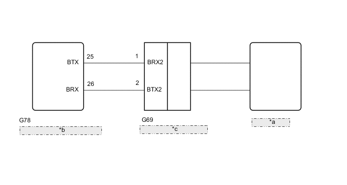
| *a | Accessory ECU |
| *b | Main Body ECU (Multiplex Network Body ECU) |
| *c | Option Connector (Accessory BERKES) |
CAUTION / NOTICE / HINT
Note
-
Before performing repairs, make sure there are no malfunctions in the power source circuit of the accessory ECU. (For details, refer to the installation procedures of the accessory manual.)
-
When using the GTS with the ignition switch off, turn a door courtesy light switch assembly on and off at intervals of 1.5 seconds or less until communication between the GTS and vehicle begins.
Tech Tips
For the circuit diagram of the accessory ECU, refer to the installation manual wiring diagram of the accessory manual.
PROCEDURE
-
CHECK ACCESSORY ECU INSTALLATION
-
Check if an accessory ECU (security ECU or remote engine starter ECU) is installed.
Result Result Proceed to Part installed A Part not installed B
B 
INITIALIZE MAIN BODY ECU (MULTIPLEX NETWORK BODY ECU) Click here
A 
-
-
CHECK HARNESS AND CONNECTOR (MAIN BODY ECU [MULTIPLEX NETWORK BODY ECU] - OPTION CONNECTOR)
-
Disconnect the G78 main body ECU (multiplex network body ECU) connector.
-
Disconnect the G69 connector of the option connector (accessory BERKES).
-
Measure the resistance according to the value(s) in the table below.
Standard Resistance Tester Connection Condition Specification Condition G78-25 (BTX) - G69-1 (BRX2) Always Below 1 Ω G78-26 (BRX) - G69-2 (BTX2) G78-25 (BTX) - Body ground Always 10 kΩ or higher G78-26 (BRX) - Body ground Result Proceed to OK NG
OK 
REPLACE OPTION CONNECTOR (ACCESSORY BERKES) WITH NEW OR NORMALLY FUNCTIONING ONE
NG
REPAIR OR REPLACE HARNESS OR CONNECTOR IN CIRCUIT CONNECTED TO POWER SOURCE
-
-
INITIALIZE MAIN BODY ECU (MULTIPLEX NETWORK BODY ECU)
Tech Tips
When an accessory ECU (security ECU or remote engine starter ECU) connected to the main body ECU (multiplex network body ECU) is removed, initialize the main body ECU (multiplex network body ECU).
-
Initialize ECU connection information
-
Connect the GTS to the DLC3.
-
Turn the ignition switch to ON.
-
Turn the GTS on.
-
Enter the following menus: Main Body / Utility / Initialize ECU Connection Information. Body Electrical
Body Electrical > Main Body > UtilityTester Display Initialization
Result Proceed to NEXT -
NEXT
-
-
CHECK FOR DTC
-
Check for DTCs.
Body Electrical > Main Body > Trouble CodesResult Result Proceed to B1269 and B126A are not output A B1269 or B126A is output (for LHD) B B1269 or B126A is output (for RHD) C
A
END
B
REPLACE MULTIPLEX NETWORK BODY ECU Click here
C
REPLACE MULTIPLEX NETWORK BODY ECU Click here
-