LIN COMMUNICATION SYSTEM TERMINALS OF ECU
-
CHECK INSTRUMENT PANEL JUNCTION BLOCK ASSEMBLY AND MAIN BODY ECU (MULTIPLEX NETWORK BODY ECU)
-
Remove the main body ECU (multiplex network body ECU).
-
for LHD:
-
for RHD:
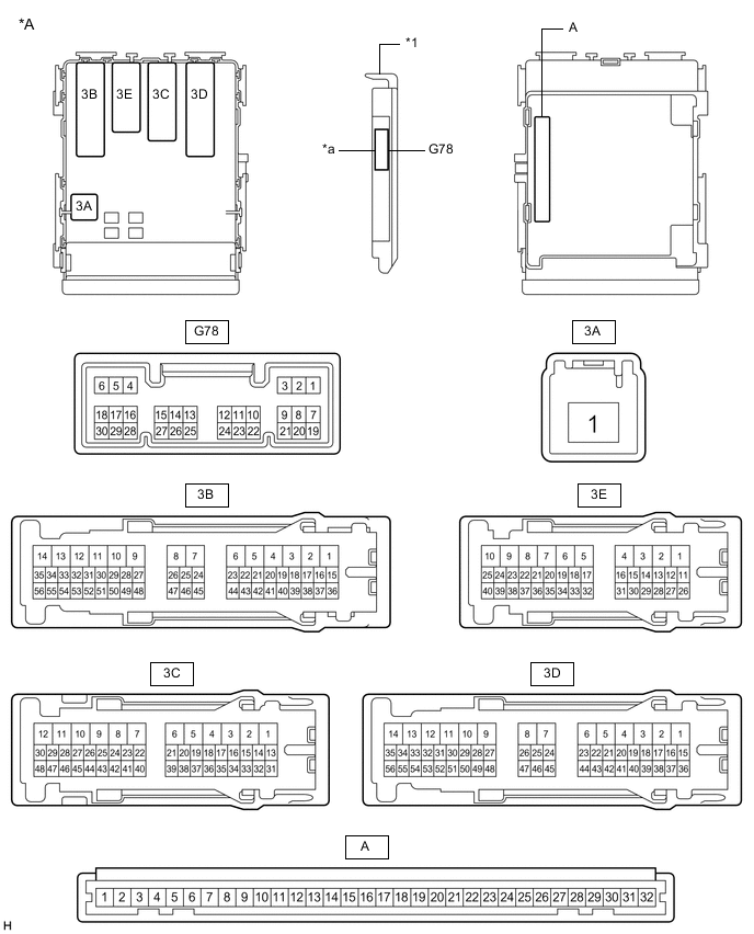
*A Main Body ECU (Multiplex Network Body ECU) with 1 Connector - - *1 Main Body ECU (Multiplex Network Body ECU) - - *a 1 Connector - - 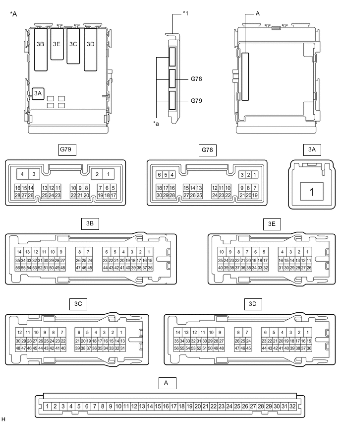
*A Main Body ECU (Multiplex Network Body ECU) with 3 Connectors - - *1 Main Body ECU (Multiplex Network Body ECU) - - *a 3 Connectors - - -
-
Measure the voltage and resistance according to the value(s) in the table below.
Tech Tips
Measure the values on the wire harness side with the connectors disconnected.
Tester Connection Wiring Color Terminal Description Condition Specified Condition A-11 (GND1) - Body ground - Ground Always Below 1 Ω A-30 (BECU) - Body ground - Battery power supply Always 11 to 14 V A-29 (ACC) - Body ground - ACC power supply Ignition switch ACC 11 to 14 V A-29 (ACC) - Body ground - ACC power supply Ignition switch off Below 1 V A-32 (IG) - Body ground - IG power supply Ignition switch ON 11 to 14 V A-32 (IG) - Body ground - IG power supply Ignition switch off Below 1 V If the result is not as specified, there may be a malfunction in the wire harness.
-
-
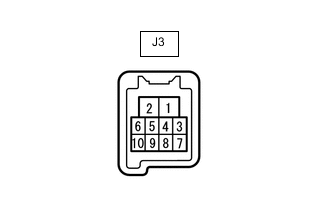
CHECK FRONT POWER WINDOW REGULATOR MOTOR ASSEMBLY LH (for LHD, w/ Jam Protection Function)
-
Disconnect the J3 front power window regulator motor assembly LH connector.
-
Measure the resistance and voltage according to the value(s) in the table below.
Terminal No. (Symbol) Wiring Color Terminal Description Condition Specified Condition J3-2 (B) - Body ground GR - Body ground Battery power supply Always 11 to 14 V J3-1 (GND) - Body ground W-B - Body ground Ground Always Below 1 Ω
-
-
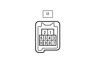
CHECK FRONT POWER WINDOW REGULATOR MOTOR ASSEMBLY RH (for RHD, w/ Jam Protection Function)
-
Disconnect the I3 front power window regulator motor assembly RH connector.
-
Measure the resistance and voltage according to the value(s) in the table below.
Terminal No. (Symbol) Wiring Color Terminal Description Condition Specified Condition I3-2 (B) - Body ground GR - Body ground Battery power supply Always 11 to 14 V I3-1 (GND) - Body ground W-B - Body ground Ground Always Below 1 Ω
-
-
CHECK SLIDING ROOF DRIVE GEAR SUB-ASSEMBLY (w/ Sliding Roof System)
-
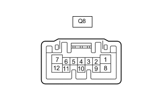
Disconnect the Q8 sliding roof drive gear sub-assembly connector.
-
Measure the resistance and voltage according to the value(s) in the table below.
Terminal No. (Symbol) Wiring Color Terminal Description Condition Specified Condition Q8-8 (B) - Body ground L - Body ground Battery power supply Always 11 to 14 V Q8-12 (E) - Body ground W-B - Body ground Ground Always Below 1 Ω
-
-
CHECK CERTIFICATION ECU (SMART KEY ECU ASSEMBLY) [w/ Entry and Start System]
-
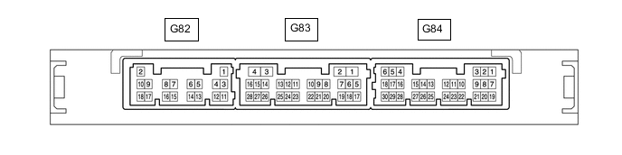
Disconnect the G82 certification ECU connector.
-
Measure the resistance and voltage according to the value(s) in the table below.
Terminal No. (Symbol) Wiring Color Terminal Description Condition Specified Condition G82-2 (+B) - Body ground W - Body ground Battery power supply Always 11 to 14 V G82-11 (E) - Body ground BR - Body ground Ground Always Below 1 Ω
-
-
CHECK ID CODE BOX (IMMOBILISER CODE BOX) [w/ Entry and Start System, w/ Multi-information Display (Dot Display Type)]
-
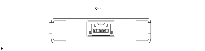
Disconnect the G44 ID code box connector.
-
Measure the resistance and voltage according to the value(s) in the table below.
Terminal No. (Symbol) Wiring Color Terminal Description Condition Specified Condition G44-1 (+B) - Body ground BE - Body ground Battery power supply Always 11 to 14 V G44-5 (GND) - Body ground B - Body ground Ground Always Below 1 Ω
-
-
CHECK STEERING LOCK ACTUATOR ASSEMBLY (w/ Entry and Start System)
-
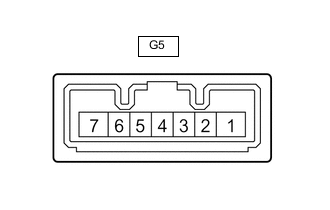
Disconnect the G5 steering lock actuator assembly connector.
-
Measure the resistance and voltage according to the value(s) in the table below.
Terminal No. (Symbol) Wiring Color Terminal Description Condition Specified Condition G5-7 (B) - Body ground L - Body ground Battery power supply Always 11 to 14 V G5-1 (GND) - Body ground W-B - Body ground Ground Always Below 1 Ω
-
-
CHECK AIR CONDITIONING AMPLIFIER ASSEMBLY (w/ Automatic Air Conditioning System)
-
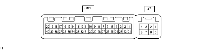
Disconnect the G81 air conditioning amplifier assembly connector.
-
Measure the resistance and voltage according to the value(s) in the table below.
Terminal No. (Symbol) Wiring Color Terminal Description Condition Specified Condition G81-1 (IG+) - Body ground GR - Body ground IG power supply Ignition switch off Below 1 V G81-1 (IG+) - Body ground GR - Body ground IG power supply Ignition switch ON 11 to 14 V G81-21 (B) - Body ground GR - Body ground Battery power supply Always 11 to 14 V G81-14 (GND) - Body ground W-B - Body ground Ground Always Below 1 Ω
-
-
CHECK AIR CONDITIONING CONTROL ASSEMBLY
-
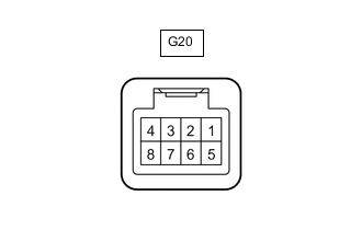
Disconnect the G20 air conditioning control assembly connector.
-
Measure the resistance and voltage according to the value(s) in the table below.
Terminal No. (Symbol) Wiring Color Terminal Description Condition Specified Condition G20-8 (IG+) - Body ground BE - Body ground IG power supply Ignition switch ON 11 to 14 V G20-8 (IG+) - Body ground BE - Body ground IG power supply Ignition switch off Below 1 V G20-5 (GND) - Body ground BR - Body ground Ground Always Below 1 Ω
-
-
CHECK RAIN SENSOR (w/ Rain Sensor)
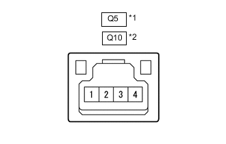
*1 for LHD *2 for RHD
-
Disconnect the Q5*1 or Q10*2 rain sensor connector.
*1: for LHD
*2: for RHD
-
Measure the voltage according to the value(s) in the table below.
for LHD Terminal No. (Symbol) Wiring Color Terminal Description Condition Specified Condition Q5-4 (SIG) - Body ground GR - Body ground IG power supply Ignition switch ON 11 to 14 V Q5-4 (SIG) - Body ground GR - Body ground IG power supply Ignition switch off Below 1 V Q5-2 (ES) - Body ground W-B - Body ground Ground circuit Always Below 1 Ω for RHD Terminal No. (Symbol) Wiring Color Terminal Description Condition Specified Condition Q10-4 (SIG) - Body ground GR - Body ground IG power supply Ignition switch ON 11 to 14 V Q10-4 (SIG) - Body ground GR - Body ground IG power supply Ignition switch off Below 1 V Q10-2 (ES) - Body ground W-B - Body ground Ground Always Below 1 Ω
-
-
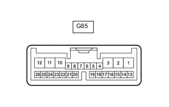
CHECK WINDSHIELD WIPER RELAY ASSEMBLY (w/ Rain Sensor)
-
Disconnect the G85 windshield wiper relay assembly connector.
-
Measure the voltage and resistance according to the value(s) in the table below.
Terminal No. (Symbol) Wiring Color Terminal Description Condition Specified Condition G85-2 (IG) - Body ground L - Body ground Battery power supply Ignition switch ON 11 to 14 V G85-2 (IG) - Body ground L - Body ground Battery power supply Ignition switch off Below 1 V G85-12 (E) - Body ground W-B - Body ground Ground Always Below 1 Ω
-
-
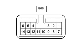
CHECK DOUBLE LOCK DOOR CONTROL RELAY ASSEMBLY (w/Double Locking System)
-
Disconnect the G66 double lock door control relay connector.
-
Measure the voltage and resistance according to the value(s) in the table below.
Terminal No. (Symbol) Wiring Color Terminal Description Condition Specified Condition G66-7 (CPUB) - Body ground BR - Body ground Battery power supply Always 11 to 14 V G66-1 (+B) - Body ground G - Body ground Battery power supply Always 11 to 14 V G66-14 (GND) - Body ground W-B - Body ground Ground Always Below 1 Ω
-