CHARGING SYSTEM TERMINALS OF ECM
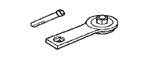 |
09820-63021 | Alternator Pulley Wrench Set |
-
TERMINAL INSPECTION
-
Measure the voltage and resistance according to the value(s) in the table below.
Tech Tips
The standard voltage of each ECM terminal is shown in the table below.
In the table, first follow the information in "Condition". Look at "Terminal No. (Symbol)" for the terminals to be inspected. The standard voltage between the terminals is shown in "Specified Condition".
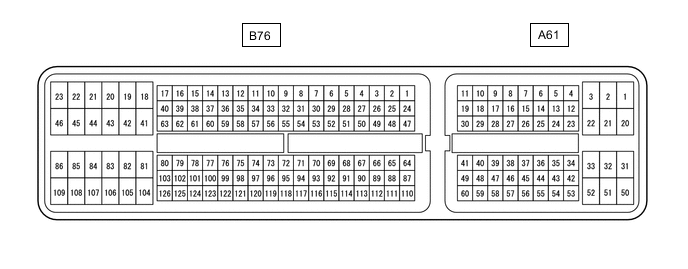
Use the illustration above as a reference for the ECM terminals.
Terminal No. (Symbol) Wiring Color Terminal Description Condition Specified Condition B76-55 (RLO) - B76-109 (E1) R - BR Generator After engine warmed up, during charging control, vehicle accelerated Pulse generation
(see waveform 1)
B76-55 (RLO) - B76-109 (E1) R - BR Generator After engine warmed up, during charging control, vehicle decelerated Pulse generation
(see waveform 2)
B76-75 (VCIB) - B76-77 (EIB) GR - L Battery current sensor assembly Ignition switch ON 4.5 to 5.5 V B76-115 (THB) - B76-77 (EIB) W - L Battery current sensor assembly Ignition switch ON 0.2 to 4.8 V B76-116 (IB) - B76-77 (EIB) R - L Wiper operation signal Ignition switch ON,
battery thermometer sensor surrounding temperature -30 to 90°C (-22 to 194°F)
0.2 to 4.8 V B76-109 (E1) - Body ground BR - Body ground Ground circuit of ECM Always Below 1 Ω A61-2 (BATT) - B76-109 (E1) W - BR Battery (for measuring the battery voltage and for the ECM memory) Always 11 to 14 V -
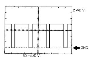
Using an oscilloscope, check waveform 1.
Tech Tips
A constant value is not output, as the duty ratio varies depending on the electrical load and battery condition.
-
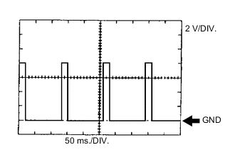
Using an oscilloscope, check waveform 2.
Tech Tips
A constant value is not output, as the duty ratio varies depending on the electrical load and battery condition.
-