CHARGING SYSTEM ON-VEHICLE INSPECTION

CAUTION / NOTICE / HINT
Note
If the battery is weak or if the engine is difficult to start, recharge the battery and perform inspections again before returning the vehicle to the customer.
PROCEDURE
-
CHECK BATTERY CONDITION
-
Check the battery for damage and deformation. If damage, deformation or leakage is found, replace the battery.
-
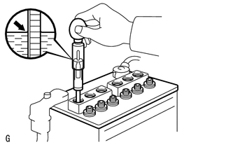
Check the electrolyte level in of each cell.
-
For maintenance-free batteries:
-
If the electrolyte level is below the lower line, replace the battery.
-
If the electrolyte level is above the lower line, check the battery voltage when cranking the engine. If the voltage is below 9.6 V, recharge or replace the battery.
Tech Tips
Before checking the battery voltage, turn off all the electrical systems (headlights, blower motor, rear defogger, etc.).
-
-
For non-maintenance-free batteries:
-
If the electrolyte level is below the lower line, add distilled water to each cell. Then, recharge the battery and check the electrolyte specific gravity.
Standard Specific Gravity 1.25 to 1.29 at 20°C (68°F) -
If the electrolyte level is above the lower line, check the battery voltage when cranking the engine. If the voltage is below 9.6 V, recharge or replace the battery.
Tech Tips
Before checking the battery voltage, turn off all electrical systems (headlights, blower motor, rear defogger, etc.).
-
-
-
Check the voltage.
-
Turn the ignition switch off and turn on the headlights for 20 to 30 seconds. This will remove the surface charge from the battery.
-
Measure the battery voltage according to the value(s) in the table below.
Standard Voltage Tester Connection Condition Specified Condition Positive (+) terminal - Negative (-) terminal 20°C (68°F) 12.5 to 12.9 V If the voltage is not as specified, charge the battery.
-
-
-
INSPECT BATTERY TERMINAL AND FUSE
-
Check that the battery terminals are not loose or corroded.
If the terminal is corroded, clean the terminal.
-
Measure the resistance of the H-fuses and fuses.
Standard Resistance Below 1 Ω If the result is not as specified, replace the fuse.
-
-
INSPECT FAN AND GENERATOR V BELT
-
INSPECT GENERATOR WIRING
-
Visually check the generator wiring.
-
Check that the wiring is in good condition.
-
-
-
CHECK FOR ABNORMAL NOISE
-
Listen for abnormal noises from the generator assembly.
-
Check that no abnormal noises are heard from the generator assembly while the engine is running.
-
-
-
INSPECT CHARGE WARNING LIGHT CIRCUIT
-
for Segment Type:
-
Turn the ignition switch to ON. Check that the charge warning light comes on.
-
Start the engine and check that the light goes off.
If the light does not operate as specified, troubleshoot the charge warning light circuit.
-
-
for TFT Type:
-
Check that nothing is displayed on the multi-information display.
-
-
-
INSPECT CHARGING CIRCUIT WITHOUT LOAD
-
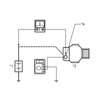
*1 Battery *2 Generator Assembly *a Terminal B Connect a voltmeter and an ammeter to the charging circuit as follows.
Tech Tips
If a battery/generator assembly tester is available, connect the tester to the charging circuit in accordance with the manufacturer's instructions.
-
Disconnect the wire from terminal B of the generator assembly and connect it to the negative (-) lead of the ammeter.
-
Connect the ammeter positive (+) lead to the terminal B of the generator assembly.
-
Connect the voltmeter positive (+) lead to the terminal B of the generator assembly.
-
Ground the voltmeter negative (-) lead.
-
-
Check the charging circuit.
-
Maintain the engine speed at 2000 rpm and check the readings on the ammeter and voltmeter.
Standard Current 10 A or higher Standard Voltage 12.1 to 15.4 V If the result is not as specified, replace the generator assembly.
Tech Tips
If the battery is not fully charged, the ammeter reading will sometimes be more than the standard current.
-
-
-
INSPECT CHARGING CIRCUIT WITH LOAD
-
With the engine running at 2000 rpm, turn the high beam headlights on and turn the heater blower switch to the "HI" position.
-
Check the reading on the ammeter.
Standard Current 30 A or higher If the ammeter reading is less than the standard current, repair the generator assembly.
Tech Tips
If the battery is fully charged, the indication will sometimes be less than the standard current. If this is the case, add more electrical load (operate the wipers, rear window defogger, etc.) and check the reading on the ammeter again.
-
-
INSPECT CHARGING CONTROL SYSTEM
-
Inspect the wire harness.
-
Disconnect the B76 ECM connector.
-
Disconnect the B61 generator assembly connector.
-
Measure the resistance according to the value(s) in the table below.
Standard Resistance Tester Connection Condition Specified Condition B76-55 (RLO) - B61-1 (RLO) Always Below 1 Ω B76-55 (RLO) or B61-1 (RLO) - Body ground and other terminals Always 10 kΩ or higher
-
-