BLIND SPOT MONITOR SYSTEM Reverse Signal Circuit
DESCRIPTION
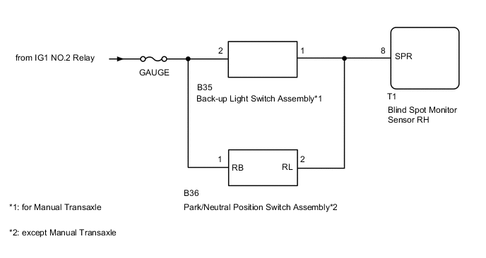
The blind spot monitor sensor RH receives a reverse signal from the park/neutral position switch assembly*1 or back-up light switch assembly*2.
-
*1: except Manual Transaxle
-
*2: for Manual Transaxle
WIRING DIAGRAM
CAUTION / NOTICE / HINT
Note
Inspect the fuses for circuits related to this system before performing the following inspection procedure.
PROCEDURE
-
CHECK VEHICLE TYPE (DISPLAY CHECK MODE)
-
Cehck the vehicle type.
Result Proceed to except Manual Transaxle for Manual Transaxle
for Manual Transaxle 
INSPECT BACK-UP LIGHT SWITCH ASSEMBLY Click here
except Manual Transaxle 
-
-
INSPECT PARK/NEUTRAL POSITION SWITCH ASSEMBLY
-
Remove the park/neutral position switch assembly.
for U760E:
for U660F:
for K111:
for K111F:
for K114F:
for U760F:
-
Inspect the park/neutral position switch assembly.
for U760E:
for U660F:
for K111:
for K111F:
for K114F:
for U760F:
Result Proceed to OK NG
NG 
REPLACE PARK/NEUTRAL POSITION SWITCH ASSEMBLY for U660F: REPLACE PARK/NEUTRAL POSITION SWITCH ASSEMBLY Click here
REPLACE PARK/NEUTRAL POSITION SWITCH ASSEMBLY for U760E: REPLACE PARK/NEUTRAL POSITION SWITCH ASSEMBLY Click here
REPLACE PARK/NEUTRAL POSITION SWITCH ASSEMBLY for K111: REPLACE PARK/NEUTRAL POSITION SWITCH ASSEMBLY Click here
REPLACE PARK/NEUTRAL POSITION SWITCH ASSEMBLY for K111F: REPLACE PARK/NEUTRAL POSITION SWITCH ASSEMBLY Click here
REPLACE PARK/NEUTRAL POSITION SWITCH ASSEMBLY for K114F: REPLACE PARK/NEUTRAL POSITION SWITCH ASSEMBLY Click here
REPLACE PARK/NEUTRAL POSITION SWITCH ASSEMBLY for U760F: REPLACE PARK/NEUTRAL POSITION SWITCH ASSEMBLY Click hereOK
-
-
CHECK HARNESS AND CONNECTOR (PARK/NEUTRAL POSITION SWITCH ASSEMBLY - BLIND SPOT MONITOR SENSOR RH AND BATTERY)
-
Disconnect the B36 park/neutral position switch assembly connector.
-
Disconnect the T1 blind spot monitor sensor RH connector.
-
Measure the voltage according to the value(s) in the table below.
Standard Voltage Tester Connection Switch Condition Specified Condition B36-1 (RB) - Body ground Ignition switch ON 11 to 14 V -
Measure the resistance according to the value(s) in the table below.
Standard Resistance Tester Connection Condition Specified Condition B36-2 (RL) - T1-8 (SPR) Always Below 1 Ω B36-2 (RL) - Body ground Always 10 kΩ or higher Result Proceed to OK NG
OK
REPLACE BLIND SPOT MONITOR SENSOR RH Click here
NG
REPAIR OR REPLACE HARNESS OR CONNECTOR
-
-
INSPECT BACK-UP LIGHT SWITCH ASSEMBLY
-
Remove the back-up light switch assembly.
for EA64F:
for EB61F:
for EB61:
for EB63F:
for EA64:
-
Inspect the back-up light switch assembly.
for EA64F:
for EB61F:
for EB61:
for EB63F:
for EA64:
Result Proceed to OK NG
NG
REPLACE BACK-UP LIGHT SWITCH ASSEMBLY for EA64F: REPLACE BACK-UP LIGHT SWITCH ASSEMBLY Click here
REPLACE BACK-UP LIGHT SWITCH ASSEMBLY for EB61F: REPLACE BACK-UP LIGHT SWITCH ASSEMBLY Click here
REPLACE BACK-UP LIGHT SWITCH ASSEMBLY for EB61: REPLACE BACK-UP LIGHT SWITCH ASSEMBLY Click here
REPLACE BACK-UP LIGHT SWITCH ASSEMBLY for EB63F: REPLACE BACK-UP LIGHT SWITCH ASSEMBLY Click here
REPLACE BACK-UP LIGHT SWITCH ASSEMBLY for EA64: REPLACE BACK-UP LIGHT SWITCH ASSEMBLY Click hereOK
-
-
CHECK HARNESS AND CONNECTOR (BACK-UP LIGHT SWITCH ASSEMBLY - NAVIGATION RECEIVER ASSEMBLY AND BATTERY)
-
Disconnect the B35 back-up light switch assembly connector.
-
Disconnect the T1 blind spot monitor sensor RH connector.
-
Measure the voltage according to the value(s) in the table below.
Standard Voltage Tester Connection Switch Condition Specified Condition B35-2 - Body ground Ignition switch ON 11 to 14 V -
Measure the resistance according to the value(s) in the table below.
Standard Resistance Tester Connection Condition Specified Condition B35-1 - T1-8 (SPR) Always Below 1 Ω B35-1 - Body ground Always 10 kΩ or higher Result Proceed to OK NG
OK
REPLACE BLIND SPOT MONITOR COVER RH Click here
NG
REPAIR OR REPLACE HARNESS OR CONNECTOR
-