REAR VIEW MONITOR SYSTEM TERMINALS OF ECU
-
TELEVISION CAMERA ASSEMBLY
-
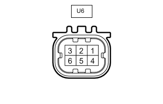
Disconnect the U6 television camera assembly connector.
-
Measure the voltage according to the value(s) in the table below.
Terminal No. (Symbol) Wiring Color Terminal Description Condition Specified Condition U6-6 (CB+) - Body ground B - Body ground Power source Within 60 seconds of turning the ignition switch to ACC 5.5 to 7.05 V -
Reconnect the U6 television camera assembly connector.
-
Measure the voltage and waveform according to the value(s) in the table below.
Terminal No. (Symbol) Wiring Color Terminal Description Condition Specified Condition U6-3 (CV+) - U6-2 (CV-) W - R Video signal Ignition switch ON
Shift lever in R
Camera lens not covered, displaying an image
Pulse generation
(See waveform 1)
Ignition switch ON
Shift lever in R
Camera lens covered, blacking out screen
Pulse generation
(See waveform 2)
Tech Tips
A waterproof connector is used for the television camera assembly. Therefore, inspect the waveform at the radio and display receiver assembly*1 or navigation ECU sub-assembly*2 with the connector connected.
-
*1: w/o Navigation System
-
*2: w/ Navigation System
-
-
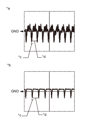
*a Waveform 1 (camera lens is not covered, displaying an image) *b Waveform 2 (camera lens is covered, blacking out the screen) *c Synchronization Signal *d Video Waveform Reference (Oscilloscope waveform):
Tech Tips
A waterproof connector is used for the television camera assembly. Therefore, inspect the waveform at the radio and display receiver assembly*1 or navigation ECU sub-assembly*2 with the connector connected.
-
*1: w/o Navigation System
-
*2: w/ Navigation System
-
Waveform 1 (camera lens is not covered, displaying an image)
Item Content Terminal No. (Symbol) U6-3 (CV+) - U6-2 (CV-) Tool Setting 200 mV/DIV., 50 μsec./DIV. Condition Ignition switch ON, shift lever in R Tech Tips
The video waveform changes according to the image sent by the television camera assembly.
-
Waveform 2 (camera lens is covered, blacking out the screen)
Item Content Terminal No. (Symbol) U6-3 (CV+) - U6-2 (CV-) Tool Setting 200 mV/DIV., 50 μsec./DIV. Condition Ignition switch ON, shift lever in R Tech Tips
The video waveform changes according to the image sent by the television camera assembly.
-
-
-
RADIO AND DISPLAY RECEIVER ASSEMBLY (w/o Navigation System)
-
NAVIGATION ECU SUB-ASSEMBLY (w/ Navigation System)