TOYOTA PARKING ASSIST-SENSOR SYSTEM(for 4 Sensor Type) Rear Clearance Sonar Sensor RH Circuit
DESCRIPTION
The ultrasonic sensor sends and receives ultrasonic waves. Based on the received wave, the sensor calculates the approximate distance between the vehicle and the obstacle, and sends the distance value as a signal to the clearance warning ECU assembly.
WIRING DIAGRAM
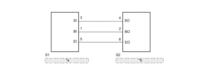
| *a | No. 3 Ultrasonic Sensor (Rear Corner Sensor RH) |
| *b | No. 3 Ultrasonic Sensor (Rear Center Sensor RH) |
PROCEDURE
-
CHECK NO. 3 ULTRASONIC SENSOR (REAR CORNER SENSOR RH)
-
Replace the No. 3 ultrasonic sensor (rear corner sensor RH) with a normally functioning sensor.
Tech Tips
All of the sensors are interchangeable. To confirm whether a sensor is functioning normally, switch it with a known good sensor from the other end of the vehicle.
-
Check the operation of the Toyota parking assist-sensor system.
Result Proceed to Toyota parking assist-sensor system normal operation Toyota parking assist-sensor system malfunction
Toyota parking assist-sensor system normal operation 
END (REAR CORNER SENSOR RH IS DEFECTIVE)
Toyota parking assist-sensor system malfunction 
-
-
CHECK HARNESS AND CONNECTOR (REAR CORNER SENSOR RH - REAR CENTER SENSOR RH)
-
Disconnect the S1 No. 3 ultrasonic sensor (rear corner sensor RH) connector.
-
Disconnect the S2 No. 3 ultrasonic sensor (rear center sensor RH) connector.
-
Measure the resistance according to the value(s) in the table below.
Standard Resistance Tester Connection Condition Specified Condition S1-3 (SI) - S2-4 (SO) Always Below 1 Ω S1-1 (BI) - S2-2 (BO) Always Below 1 Ω S1-5 (EI) - S2-6 (EO) Always Below 1 Ω S1-3 (SI) - Body ground Always 10 kΩ or higher S1-1 (BI) - Body ground Always 10 kΩ or higher S1-5 (EI) - Body ground Always 10 kΩ or higher Result Proceed to OK NG
OK
PROCEED TO NEXT SUSPECTED AREA SHOWN IN PROBLEM SYMPTOMS TABLE Click here
NG
REPAIR OR REPLACE HARNESS OR CONNECTOR
-