TOYOTA PARKING ASSIST-SENSOR SYSTEM(for 4 Sensor Type) Reverse Signal Circuit
DESCRIPTION
The clearance warning ECU assembly receives a reverse shift position signal from the park/neutral position switch assembly*1 or back-up light switch assembly*2.
-
*1: except Manual Transaxle
-
*2: for Manual Transaxle
WIRING DIAGRAM
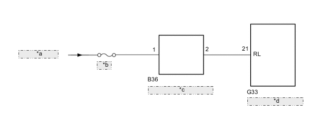
| *a | IG1 NO.2 Relay |
| *b | GAUGE |
| *c | Park/Neutral Position Switch Assembly |
| *d | Clearance Warning ECU Assembly |
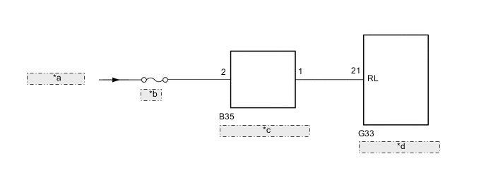
| *a | IG1 NO.2 Relay |
| *b | GAUGE |
| *c | Back-up Light Switch Assembly |
| *d | Clearance Warning ECU Assembly |
PROCEDURE
-
CHECK CLEARANCE WARNING ECU ASSEMBLY (REVERSE SIGNAL)
-
Disconnect the G33 clearance warning ECU assembly connector.
-
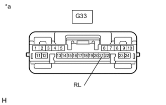
*a Front view of wire harness connector
(to Clearance Warning ECU Assembly)
Measure the voltage according to the value(s) in the table below.
Standard Voltage Tester Connection Switch Condition Specified Condition G33-21 (RL) - Body ground Ignition switch ON
Shift lever in R
11 to 14 V G33-21 (RL) - Body ground Ignition switch ON
Shift lever in any position except R
Below 1 V Result Result OK NG (except Manual Transaxle) NG (for Manual Transaxle)
OK 
PROCEED TO NEXT SUSPECTED AREA SHOWN IN PROBLEM SYMPTOMS TABLE Click here
NG (for Manual Transaxle) 
CHECK HARNESS AND CONNECTOR (CLEARANCE WARNING ECU ASSEMBLY - BACK-UP LIGHT SWITCH ASSEMBLY) Click here
NG (except Manual Transaxle) 
-
-
CHECK HARNESS AND CONNECTOR (CLEARANCE WARNING ECU ASSEMBLY - PARK/NEUTRAL POSITION SWITCH ASSEMBLY)
-
Disconnect the G33 clearance warning ECU assembly connector.
-
Disconnect the B36 park/neutral position switch assembly connector.
-
Measure the resistance according to the value(s) in the table below.
Standard Resistance Tester Connection Condition Specified Condition G33-21 (RL) - B36-2 Always Below 1 Ω G33-21 (RL) - Body ground Always 10 kΩ or higher Result Proceed to OK NG
OK
REPLACE PARK/NEUTRAL POSITION SWITCH ASSEMBLY for U660F: Click here for U760E: Click here for U760F: Click here for K111: Click here for K111F: Click here for K114F: Click here
NG
REPAIR OR REPLACE HARNESS OR CONNECTOR
-
-
CHECK HARNESS AND CONNECTOR (CLEARANCE WARNING ECU ASSEMBLY - BACK-UP LIGHT SWITCH ASSEMBLY)
-
Disconnect the G33 clearance warning ECU assembly connector.
-
Disconnect the B35 back-up light switch assembly connector.
-
Measure the resistance according to the value(s) in the table below.
Standard Resistance Tester Connection Condition Specified Condition G33-21 (RL) - B35-1 Always Below 1 Ω G33-21 (RL) - Body ground Always 10 kΩ or higher Result Proceed to OK NG
OK
REPLACE BACK-UP LIGHT SWITCH ASSEMBLY for EA64: Click here for EA64F: Click here for EB61: Click here for EB61F: Click here for EB63: Click here for EB63F: Click here
NG
REPAIR OR REPLACE HARNESS OR CONNECTOR
-