TOYOTA PARKING ASSIST-SENSOR SYSTEM(for 4 Sensor Type) Taillight Relay Circuit
DESCRIPTION
This is the power source circuit of the clearance warning ECU assembly.
WIRING DIAGRAM
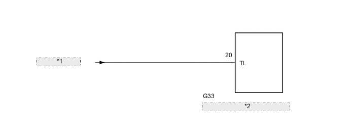
| *1 | from PANEL Fuse |
| *2 | Clearance Warning ECU Assembly |
CAUTION / NOTICE / HINT
Note
Inspect the fuses for circuits related to this system before performing the following inspection procedure.
PROCEDURE
-
CHECK TAILLIGHT
-
Turn the light control switch to the TAIL position.
-
Check that the taillight turns on.
OK Taillight turns on. Result Proceed to OK NG
NG 
GO TO LIGHTING SYSTEM Click here
OK 
-
-
CHECK HARNESS AND CONNECTOR (CLEARANCE WARNING ECU ASSEMBLY - BATTERY)
-
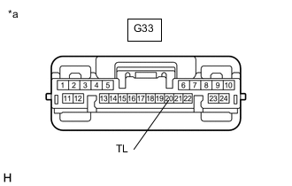
*a Front view of wire harness connector
(to Clearance Warning ECU Assembly)
Disconnect the G33 clearance warning ECU assembly connector.
-
Measure the voltage according to the value(s) in the table below.
Standard Voltage Tester Connection Switch Condition Specified Condition G33-20 (TL) - Body ground Ignition switch ON, light control switch TAIL 11 to 14 V Ignition switch ON, light control switch off Below 1 V Result Proceed to OK NG
OK
PROCEED TO NEXT SUSPECTED AREA SHOWN IN PROBLEM SYMPTOMS TABLE Click here
NG
REPAIR OR REPLACE HARNESS OR CONNECTOR
-