TOYOTA PARKING ASSIST-SENSOR SYSTEM(for 4 Sensor Type) OPERATION CHECK
-
MALFUNCTION BUZZER
-
Ultrasonic sensor open circuit
-
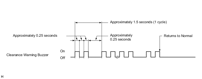
If an open circuit is detected between the ultrasonic sensors and the clearance warning ECU, or if a sensor malfunction is detected, the clearance warning buzzer sounds to indicate a malfunction as shown in the illustration.
Tech Tips
When a malfunction is detected, the buzzer shown in the illustration continues to sound.
-
-
-
MALFUNCTION DISPLAY (TELLTALE LIGHT ASSEMBLY)
-
Open circuit indication
-
If there is an open circuit between the ultrasonic sensor and the clearance warning ECU assembly or a sensor is malfunctioning, the malfunction is displayed as shown in the illustration.
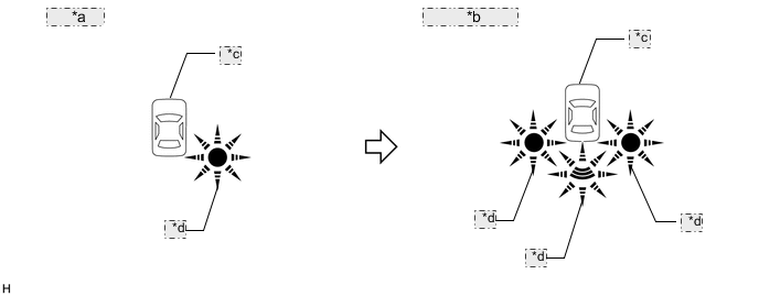
*a 5 cycles: *b After 5 cycles: *c Not illuminated *d Blinking Tech Tips
-
The example shows an open circuit in the ultrasonic sensor (rear corner sensor RH).
-
The rear right detection area blinks and the other indicator areas and the vehicle mark are not illuminated (5 cycles).
-
The rear right detection area blinks and the vehicle mark is not illuminated (after 5 cycles).
-
-
-
Frozen indication
-
If a sensor is covered with foreign matter, such as mud or snow, the affected sensor is displayed as shown in the illustration.
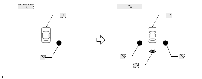
*a 5 cycles: *b After 5 cycles: *c Not illuminated *d Illuminated Tech Tips
-
The example shows that the ultrasonic sensor (rear corner sensor RH) is covered with foreign matter.
-
The rear right detection area illuminates and the other indicator areas and the vehicle mark are not illuminated (5 cycles).
-
All indicator areas illuminate and the vehicle mark is not illuminated (after 5 cycles).
-
-
-
-
DETECTION RANGE MEASUREMENT
-
Detection range measurement
Note
Make sure that the vehicle does not move by applying the parking brake firmly.
-
Turn the ignition switch to ON.
-
Move the shift lever to R to check the ultrasonic sensors.
-
-
Turn the clearance sonar main switch on.
-
Move a 60 mm (2.36 in.) diameter pole near each sensor to measure its detection range.
Note
These detection ranges are applicable when positioning the 60 mm (2.36 in.) diameter pole parallel or perpendicular to the ground. The detection range varies depending on the measuring method and type of obstacle (such as walls).
Tech Tips
Have an assistant move the pole.
-
Rear center sensor detection range
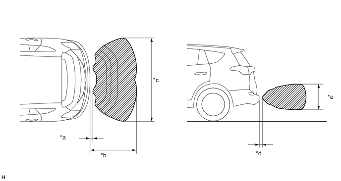
*a Approximately 200 mm (7.87 in.) *b Approximately 1000 mm (39.4 in.) *c Approximately 1800 mm (70.9 in.) *d Approximately 200 mm (7.87 in.) *e Approximately 500 mm (19.7 in.) - - -
Rear corner sensor detection range
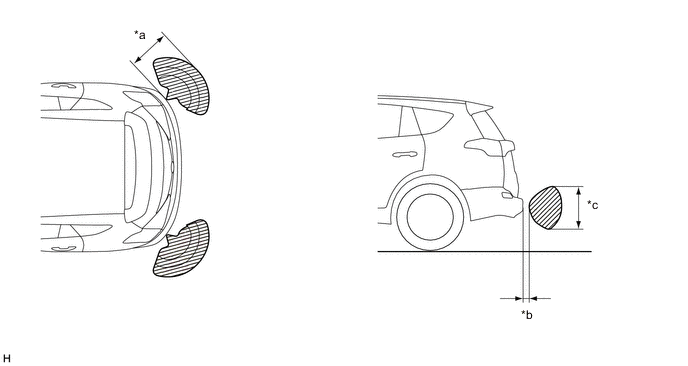
*a Approximately 500 mm (19.7 in.) *b Approximately 200 mm (7.87 in.) *c Approximately 500 mm (19.7 in.) - -
-
-
When the ultrasonic sensors (rear corner sensor) have detected an obstacle, check the displays and check that the buzzer sounds.
Operation Condition Ignition Switch Clearance Sonar Main Switch Shift Lever Position ON On R 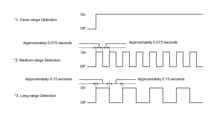
Rear Corner Detection Range Detection Range During Judgment Obstacle *1
Close-range detection
Within 300 +/- 30 mm (11.8 +/- 1.18 in.)
Buzzer: Sounds continuously 60 mm (2.36 in.) diameter pole *2
Medium-range detection
300 +/- 30 to 400 +/- 40 mm (11.8 +/- 1.18 to 15.7 +/- 1.57 in.)
Buzzer: Sounds intermittently (On: 0.075 seconds / Off: 0.075 seconds) 60 mm (2.36 in.) diameter pole *3
Long-range detection
400 +/- 40 to 500 +/- 50 mm (15.7 +/- 1.57 to 19.7 +/- 1.97 in.)
Buzzer: Sounds intermittently (On: 0.15 seconds / Off: 0.15 seconds) 60 mm (2.36 in.) diameter pole Tech Tips
Ultrasonic waves are used to measure the detection range; however, the detection range may vary depending on the ambient temperature.
-
When the ultrasonic sensors (rear center sensor) have detected an obstacle, check the displays and check that the buzzer sounds.
Operation Condition Ignition Switch Clearance Sonar Main Switch Shift Lever Position ON On R 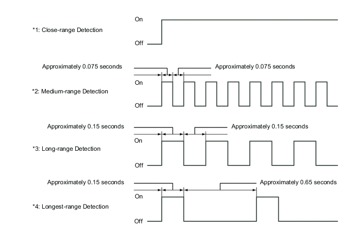
Rear Corner Detection Range Detection Range During Judgment Obstacle *1
Close-range detection
Within 300 +/- 30 mm (11.8 +/- 1.18 in.)
Buzzer: Sounds continuously 60 mm (2.36 in.) diameter pole *2
Medium-range detection
300 +/- 30 to 400 +/- 40 mm (11.8 +/- 1.18 to 15.7 +/- 1.57 in.)
Buzzer: Sounds intermittently (On: 0.075 seconds / Off: 0.075 seconds) 60 mm (2.36 in.) diameter pole *3
Long-range detection
400 +/- 40 to 500 +/- 50 mm (15.7 +/- 1.57 to 19.7 +/- 1.97 in.)
Buzzer: Sounds intermittently (On: 0.15 seconds / Off: 0.15 seconds) 60 mm (2.36 in.) diameter pole *4
4. Longest-range detection
600 +/- 60 to 1500 +/- 150 mm (23.6 +/- 2.36 to 59.1 +/- 5.91 in.) (To the wall)
Buzzer: Sounds intermittently (On: 0.15 seconds / Off: 0.65 seconds) Wall Tech Tips
Ultrasonic waves are used to measure the detection range; however, the detection range may vary depending on the ambient temperature.
-
Check the indicator and buzzer, when the rear center sensors and rear corner sensors have detectedan obstacle.
Operation Condition Ignition Switch Clearance Sonar Main Switch Shift Lever Position ON On R Buzzer Detection Range Indicator Displayed 1. Close-range detection Sounds continuously 2. Medium-range detection Sounds intermittently
(On: 0.075 seconds./Off: 0.075 seconds.)
3. Long-range detection Sounds intermittently
(On: 0.15 seconds./Off: 0.15 seconds.)
4. Maximum Long-range detection Sounds intermittently
(On: 0.15 seconds./Off: 0.65 seconds.)
Clearance Warning Indicator Detection Range Indicator Displayed 1. Close-range detection Corner indicator(s) are illuminated and/or back indicator is illuminated 2. Medium-range detection Corner indicator(s) are blinking and/or back indicator is blinking 3. Long-range detection Corner indicator(s) are blinking and/or back indicator is blinking 4. Maximum Long-range detection Back indicator is blinking 
*A Telltale Light Assembly - - *1 Corner Indicator *2 Rear Center Indicator Tech Tips
Ultrasonic waves are used to measure the detection range; however, the detection range may vary depending on the ambient temperature.
-