TOYOTA PARKING ASSIST-SENSOR SYSTEM(for 4 Sensor Type) SYSTEM DESCRIPTION
-
GENERAL
-
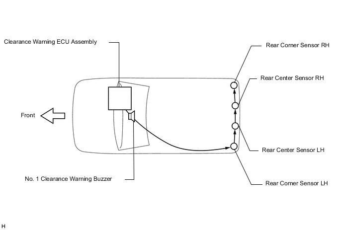
This system uses ultrasonic sensors to detect obstacles at the rear of the vehicle. If an obstacle is detected, the system then informs the driver of the distance between the sensor and obstacle by sounding a buzzer.
-
-
FUNCTION OF COMPONENTS
Component Function No. 3 Ultrasonic Sensor Detects the distance between the vehicle and an obstacle No. 1 Clearance Warning Buzzer Sounds to inform the driver according to the distance to an obstacle Telltale Light Assembly (Clearance Sonar Main Switch) Operating this switch enables, disables or cuts off the operation of the Toyota parking assist-sensor system Clearance Warning ECU Assembly Judges the approximate distance between the vehicle and an obstacle based on the signals from the ultrasonic sensors and sounds the buzzer. Back-up Light Switch Assembly*1
Park/Neutral Position Switch Assembly*2
Transmits a shift position signal to the clearance warning ECU assembly
-
*1: for Manual Transaxle
-
*2: except Manual Transaxle
-
-
OPERATION EXPLANATION
-
The operating conditions of each ultrasonic sensor differ according to the installation position as shown in the table below.
Installation Position Operating Condition Rear Center Sensor
-
Ignition switch is ON.
-
Telltale light assembly (clearance sonar main switch) is on.
-
Shift lever is in R.
When the system operates, the clearance warning ECU assembly transmits ultrasonic waves from the ultrasonic sensors. If these waves encounter an obstacle within one or more of the sensor ranges, the waves are reflected back to the sensors, which transmit them to the clearance warning ECU assembly.
Based on this information, the clearance warning ECU assembly sends signals to the clearance warning buzzer. The approximate distance between the vehicle and the obstacle is then indicated, and the buzzer sounds.
-
-
-
COMMUNICATION SIGNALS OF COMPONENTS
Tech Tips
-
Allocation refers to the process of the clearance warning ECU assembly setting aside IDs for the sensors.
-
The vehicle has the sensors arranged in 1 group. There is a rear series. The sensors are connected in a "daisy chain".
-
Initialization mode:
An ID is allocated to each sensor and sensor diagnosis is performed.
-
When the initial check is operating (the ignition switch is ON) and the telltale light assembly (clearance sonar main switch) is on, the clearance warning ECU assembly provides power to the first sensors in the series (rear corner sensor LH).
-
After the power is supplied, the rear center sensor LH enters standby mode to receive an ID from the ECU. When a certain amount of time has elapsed, the ECU sends an ID allocation signal to these sensors.
-
The rear center sensor LH receives the ID allocation signal from the ECU and performs self-diagnosis. When the sensor self-diagnosis is complete, the ECU sends an ID allocation confirmation signal to the sensor.
-
After the ID allocation confirmation is performed, the ECU provides power to the second sensor in the series (rear center sensor LH) via the first sensor. In the same manner as the first sensor, the second sensor enters standby mode. When a certain amount of time has elapsed, the ECU sends an ID allocation signal to the second sensor. Initialization ends when ID allocation to both ultrasonic sensors is complete.
-
-
Detection mode:
After initialization mode is completed, the system switches into detection mode. In detection mode, the clearance warning ECU assembly sends information request signals and sensor activation signals to the ultrasonic sensors and receives detection result signals from the sensors.
-
The ECU regularly sends ID signals, information request signals, and sensor activation signals to each ultrasonic sensor according to the communication schedule.
-
When a certain amount of time has elapsed (sensor detection operation is completed), the ECU sends an ID signal to the sensor to receive a detection result signal.
-
The ultrasonic sensor sends a detection result signal or detection information signal to the ECU.
-
The above operation is performed repeatedly for each ultrasonic sensor.
-
-