NAVIGATION SYSTEM(for SD) Microphone Circuit between Microphone and Navigation Receiver Assembly
DESCRIPTION
This circuit sends a microphone signal from the telephone microphone assembly to the navigation receiver assembly.
It also supplies power from the navigation receiver assembly to the telephone microphone assembly.
WIRING DIAGRAM
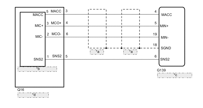
| *a | Shielded |
| *b | Telephone Microphone Assembly |
| *c | Navigation Receiver Assembly |
| *d | Map Light Assembly |
CAUTION / NOTICE / HINT
Note
Check that the wire harness is properly installed and does not have any sharp bends, pinching or loose connections.
PROCEDURE
-
CHECK HARNESS AND CONNECTOR (NAVIGATION RECEIVER ASSEMBLY - MAP LIGHT ASSEMBLY)
-
Disconnect the G139 navigation receiver assembly connector.
-
Disconnect the Q16 map light assembly connector.
-
Measure the resistance according to the value(s) in the table below.
Standard Resistance Tester Connection Condition Specified Condition G139-4 (MACC) - Q16-3 (MACC) Always Below 1 Ω G139-5 (MIN+) - Q16-4 (MCO+) Always Below 1 Ω G139-19 (MIN-) - Q16-6 (MCO-) Always Below 1 Ω G139-6 (SNS2) - Q16-5 (SNS2) Always Below 1 Ω G139-4 (MACC) - Body ground Always 10 kΩ or higher G139-5 (MIN+) - Body ground Always 10 kΩ or higher G139-19 (MIN-) - Body ground Always 10 kΩ or higher G139-18 (SGND) - Body ground Always 10 kΩ or higher G139-6 (SNS2) - Body ground Always 10 kΩ or higher Result Proceed to OK NG
NG 
REPAIR OR REPLACE HARNESS OR CONNECTOR
OK 
-
-
INSPECT MAP LIGHT ASSEMBLY
-
Remove the map light assembly.
-
Remove the telephone microphone assembly.
-
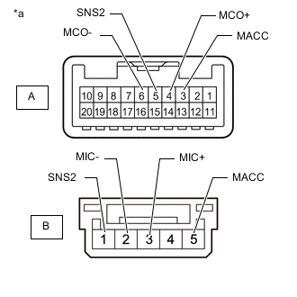
*a Component without harness connected
(Map Light Assembly)
Measure the resistance according to the value(s) in the table below.
Standard Resistance Tester Connection Condition Specified Condition A-3 (MACC) - B-5 (MACC) Always Below 1 Ω A-4 (MCO+) - B-3 (MIC+) Always Below 1 Ω A-5 (SNS2) - B-1 (SNS2) Always Below 1 Ω A-6 (MCO-) - B-2 (MIC-) Always Below 1 Ω A-3 (MACC) - A-4 (MCO+) Always 10 kΩ or higher A-3 (MACC) - A-5 (SNS2) Always 10 kΩ or higher A-3 (MACC) - A-6 (MCO-) Always 10 kΩ or higher A-4 (MCO+) - A-5 (SNS2) Always 10 kΩ or higher A-4 (MCO+) - A-6 (MCO-) Always 10 kΩ or higher A-5 (SNS2) - A-6 (MCO-) Always 10 kΩ or higher Result Proceed to OK NG
NG
REPLACE MAP LIGHT ASSEMBLY Click here
OK
-
-
CHECK TELEPHONE MICROPHONE ASSEMBLY
-
Replace the telephone microphone assembly with a known good.
-
Check if the same problem occurs again.
OK Malfunction disappears. Result Proceed to OK NG
OK
END (TELEPHONE MICROPHONE ASSEMBLY IS DEFECTIVE)
NG
REPLACE NAVIGATION RECEIVER ASSEMBLY Click here
-