NAVIGATION SYSTEM(for SD) Reverse Signal Circuit
DESCRIPTION
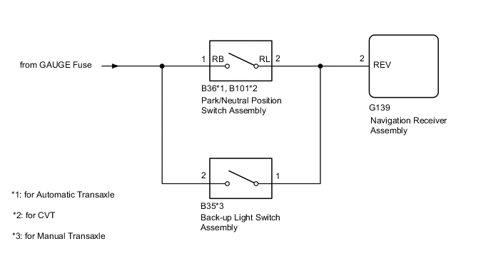
The navigation receiver assembly a reverse signal from the park/neutral position switch assembly*1 or back-up light switch assembly*2 to use for adjusting the vehicle position on the display.
-
*1: except Manual Transaxle
-
*2: for Manual Transaxle
WIRING DIAGRAM
CAUTION / NOTICE / HINT
Note
Check that the wire harness is properly installed and does not have any sharp bends, pinching or loose connections.
PROCEDURE
-
CHECK VEHICLE SIGNAL (OPERATION CHECK)
-
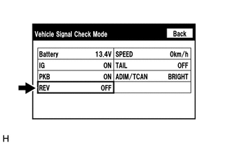
Enter the "Vehicle Signal Check Mode" screen.
Refer to check Vehicle Signal in Operation Check.
-
Check that the display changes between ON and OFF according to the shift lever position.
OK Shift Lever Position Display R ON Except R OFF Tech Tips
This display is updated once per second. As a result, it is normal for the display to lag behind the actual shift lever position.
Result Proceed to OK NG
OK 
PROCEED TO NEXT SUSPECTED AREA SHOWN IN PROBLEM SYMPTOMS TABLE Click here
NG 
-
-
CHECK NAVIGATION RECEIVER ASSEMBLY (REVERSE SIGNAL)
-
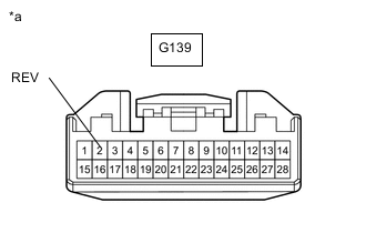
*a Front view of wire harness connector
(to Navigation Receiver Assembly)
Disconnect the navigation receiver assembly connector.
-
Measure the voltage according to the value(s) in the table below.
Standard Voltage Tester Connection Switch Condition Specified Condition G139-2 (REV) - Body ground Engine switch on (IG), shift lever in R 11 to 14 V G139-2 (REV) - Body ground Engine switch on (IG), shift lever any position other than in R Below 1 V Result Proceed to OK NG (for Automatic Transaxle) NG (for CVT) NG (for Manual Transaxle)
OK
PROCEED TO NEXT SUSPECTED AREA SHOWN IN PROBLEM SYMPTOMS TABLE Click here
NG (for CVT) 
CHECK HARNESS AND CONNECTOR (NAVIGATION RECEIVER ASSEMBLY - PARK/NEUTRAL POSITION SWITCH ASSEMBLY) Click here
NG (for Manual Transaxle)
CHECK HARNESS AND CONNECTOR (NAVIGATION RECEIVER ASSEMBLY - BACK-UP LIGHT SWITCH ASSEMBLY) Click here
NG (for Automatic Transaxle)
-
-
CHECK HARNESS AND CONNECTOR (NAVIGATION RECEIVER ASSEMBLY - PARK/NEUTRAL POSITION SWITCH ASSEMBLY)
-
Disconnect the G139 navigation receiver assembly connector.
-
Disconnect the B36 park/neutral position switch assembly connector.
-
Measure the resistance according to the value(s) in the table below.
Standard Resistance Tester Connection Condition Specified Condition G139-2 (REV) - B36-2 (RL) Always Below 1 Ω G139-2 (REV) - Body ground Always 10 kΩ or higher Result Proceed to OK NG
NG
REPAIR OR REPLACE HARNESS OR CONNECTOR
OK
-
-
CHECK HARNESS AND CONNECTOR (PARK/NEUTRAL POSITION SWITCH ASSEMBLY - BATTERY)
-
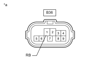
*a Front view of wire harness connector
(to Park/Neutral Position Switch Assembly)
Disconnect the park/neutral position switch assembly connector.
-
Measure the voltage according to the value(s) in the table below.
Standard Voltage Tester Connection Switch Condition Specified Condition B36-1 (RB) - Body ground Engine switch on (IG) 11 to 14 V Result Proceed to OK NG
OK
REPLACE PARK/NEUTRAL POSITION SWITCH ASSEMBLY for U760F: REPLACE PARK/NEUTRAL POSITION SWITCH ASSEMBLY Click here
REPLACE PARK/NEUTRAL POSITION SWITCH ASSEMBLY for U660F: REPLACE PARK/NEUTRAL POSITION SWITCH ASSEMBLY Click hereNG
REPAIR OR REPLACE HARNESS OR CONNECTOR
-
-
CHECK HARNESS AND CONNECTOR (NAVIGATION RECEIVER ASSEMBLY - PARK/NEUTRAL POSITION SWITCH ASSEMBLY)
-
Disconnect the G139 navigation receiver assembly connector.
-
Disconnect the B101 park/neutral position switch assembly connector.
-
Measure the resistance according to the value(s) in the table below.
Standard Resistance Tester Connection Condition Specified Condition G139-2 (REV) - B101-2 (RL) Always Below 1 Ω G139-2 (REV) - Body ground Always 10 kΩ or higher Result Proceed to OK NG
NG
REPAIR OR REPLACE HARNESS OR CONNECTOR
OK
-
-
CHECK HARNESS AND CONNECTOR (PARK/NEUTRAL POSITION SWITCH ASSEMBLY - BATTERY)
-
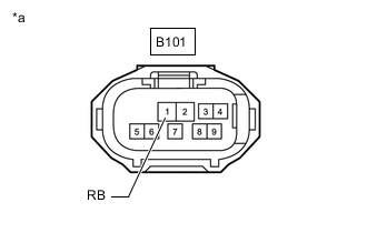
*a Front view of wire harness connector
(to Park/Neutral Position Switch Assembly)
Disconnect the park/neutral position switch assembly connector.
-
Measure the voltage according to the value(s) in the table below.
Standard Voltage Tester Connection Switch Condition Specified Condition B101-1 (RB) - Body ground Engine switch on (IG) 11 to 14 V Result Proceed to OK NG
OK
REPLACE PARK/NEUTRAL POSITION SWITCH ASSEMBLY Click here
NG
REPAIR OR REPLACE HARNESS OR CONNECTOR
-
-
CHECK HARNESS AND CONNECTOR (NAVIGATION RECEIVER ASSEMBLY - BACK-UP LIGHT SWITCH ASSEMBLY)
-
Disconnect the G139 navigation receiver assembly connector.
-
Disconnect the B35 back-up light switch assembly connector.
-
Measure the resistance according to the value(s) in the table below.
Standard Resistance Tester Connection Condition Specified Condition G139-2 (REV) - B35-1 Always Below 1 Ω G139-2 (REV) - Body ground Always 10 kΩ or higher Result Proceed to OK NG
NG
REPAIR OR REPLACE HARNESS OR CONNECTOR
OK
-
-
CHECK HARNESS AND CONNECTOR (BACK-UP LIGHT SWITCH ASSEMBLY - BATTERY)
-
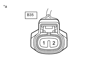
*a Front view of wire harness connector
(to Back-up Light Switch Assembly)
Disconnect the back-up light switch assembly connector.
-
Measure the voltage according to the value(s) in the table below.
Standard Voltage Tester Connection Switch Condition Specified Condition B35-2 - Body ground Engine switch on (IG) 11 to 14 V Result Proceed to OK NG
OK
REPLACE BACK-UP LIGHT SWITCH ASSEMBLY for EB61: REPLACE BACK-UP LIGHT SWITCH ASSEMBLY Click here
REPLACE BACK-UP LIGHT SWITCH ASSEMBLY for EA64F: REPLACE BACK-UP LIGHT SWITCH ASSEMBLY Click hereNG
REPAIR OR REPLACE HARNESS OR CONNECTOR
-