NAVIGATION SYSTEM(for SD) Mute Signal Circuit between Navigation Receiver Assembly and Stereo Component Amplifier
SYSTEM DESCRIPTION
This circuit sends a signal to the stereo component amplifier assembly to mute noise. Because of that, the noise produced by changing the sound source ceases.
If there is an open in the circuit, noise can be heard from the speakers when changing the sound source.
If there is a short in the circuit, even though the stereo component amplifier assembly is functioning normally, no sound or only an extremely faint sound can be heard.
WIRING DIAGRAM
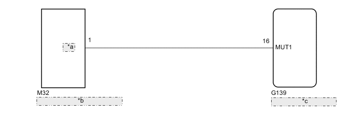
| *a | MUTE |
| *b | Stereo Component Amplifier Assembly |
| *c | Navigation Receiver Assembly |
CAUTION / NOTICE / HINT
Note
Check that the wire harness is properly installed and does not have any sharp bends, pinching or loose connections.
PROCEDURE
-
CHECK STEREO COMPONENT AMPLIFIER ASSEMBLY
-
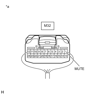
*a Component with harness connected
(Stereo Component Amplifier Assembly)
Measure the voltage according to the value(s) in the table below.
Standard Voltage Tester Connection Switch Condition Specified Condition M32-1 (MUTE) - Body ground Ignition switch ACC, audio system playing→ Changing modes Above 3.5 V→ Below 1 V Result Proceed to OK NG
OK 
PROCEED TO NEXT SUSPECTED AREA SHOWN IN PROBLEM SYMPTOMS TABLE Click here
NG 
-
-
CHECK HARNESS AND CONNECTOR (NAVIGATION RECEIVER ASSEMBLY - STEREO COMPONENT AMPLIFIER ASSEMBLY)
-
Disconnect the G139 navigation receiver assembly connector.
-
Disconnect the M32 stereo component amplifier assembly connector.
-
Measure the resistance according to the value(s) in the table below.
Standard Resistance Tester Connection Condition Specified Condition G139-16 (MUT1) - M32-1 (MUTE) Always Below 1 Ω G139-16 (MUT1) - Body ground Always 10 kΩ or higher Result Proceed to OK NG
NG
REPAIR OR REPLACE HARNESS OR CONNECTOR
OK
-
-
CHECK STEREO COMPONENT AMPLIFIER ASSEMBLY (OUTPUT SIGNAL)
-
Disconnect the navigation receiver assembly connector.
-
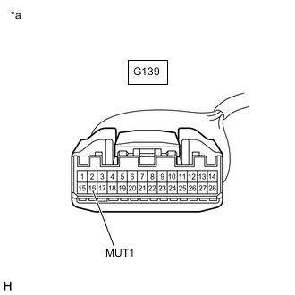
*a Front view of wire harness connector
(to Navigation Receiver Assembly)
Measure the voltage according to the value(s) in the table below.
Standard Voltage Tester Connection Switch Condition Specified Condition G139-16 (MUT1) - Body ground Ignition switch ACC, audio system playing→ Changing modes Above 3.5 V→ Below 1 V Result Proceed to OK NG
OK
REPLACE NAVIGATION RECEIVER ASSEMBLY Click here
NG
REPLACE STEREO COMPONENT AMPLIFIER ASSEMBLY Click here
-