NAVIGATION SYSTEM(for Radio and Display Type) Vehicle Speed Signal Circuit between Radio Receiver and Extension Module
DESCRIPTION
The navigation ECU receives a vehicle speed signal from the radio and display receiver assembly and information from the navigation antenna assembly, and then adjusts vehicle position.
WIRING DIAGRAM
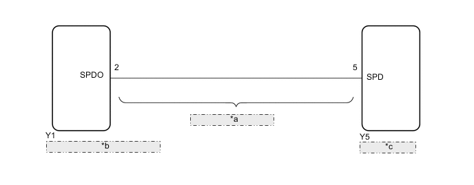
| *a | No. 1 Navigation Wire |
| *b | Radio and Display Receiver Assembly |
| *c | Navigation ECU |
CAUTION / NOTICE / HINT
Note
Check that the wire harness is properly installed and does not have any sharp bends, pinching or loose connections.
PROCEDURE
-
CHECK NO. 1 NAVIGATION WIRE (RADIO AND DISPLAY RECEIVER ASSEMBLY - NAVIGATION ECU)
-
Disconnect the Y1 radio and display receiver assembly connector.
-
Disconnect the Y5 navigation ECU connector.
-
Measure the resistance according to the value(s) in the table below.
Standard Resistance Tester Connection Condition Specified Condition Y1-2 (SPDO) - Y5-5 (SPD) Always Below 1 Ω Y1-2 (SPDO) - Body ground Always 10 kΩ or higher Result Proceed to OK NG
OK 
PROCEED TO NEXT SUSPECTED AREA SHOWN IN PROBLEM SYMPTOMS TABLE Click here
NG
REPLACE NO. 1 NAVIGATION WIRE Click here
-