NAVIGATION SYSTEM(for Radio and Display Type) Navigation Voice Circuit
DESCRIPTION
This circuit is used when the voice guidance in the navigation system is on or an incoming cellular phone voice in the "Bluetooth" hands-free system is heard.
Using this circuit, the radio and display receiver assembly sends the signals to the stereo component amplifier assembly.
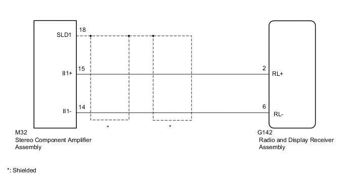
WIRING DIAGRAM
CAUTION / NOTICE / HINT
Note
Check that the wire harness is properly installed and does not have any sharp bends, pinching or loose connections.
PROCEDURE
-
CHECK HARNESS AND CONNECTOR (RADIO AND DISPLAY RECEIVER ASSEMBLY - STEREO COMPONENT AMPLIFIER ASSEMBLY)
-
Disconnect the G142 radio and display receiver assembly connector.
-
Disconnect the M32 stereo component amplifier connector.
-
Measure the resistance according to the value(s) in the table below.
Standard Resistance Tester Connection Condition Specified Condition M32-15 (II1+) - G142-2 (RL+) Always Below 1 Ω M32-14 (II1-) - G142-6 (RL-) Always Below 1 Ω M32-15 (II1+) - Body ground Always 10 kΩ or higher M32-14 (II1-) - Body ground Always 10 kΩ or higher M32-18 (SLD1) - Body ground Always 10 kΩ or higher Result Proceed to OK NG
OK 
PROCEED TO NEXT SUSPECTED AREA SHOWN IN PROBLEM SYMPTOMS TABLE Click here
NG
REPAIR OR REPLACE HARNESS OR CONNECTOR
-