NAVIGATION SYSTEM(for Radio and Display Type), Diagnostic DTC:B1579
| DTC Code | DTC Name |
|---|---|
| B1579 | Voice Recognition Microphone Disconnected |
DESCRIPTION
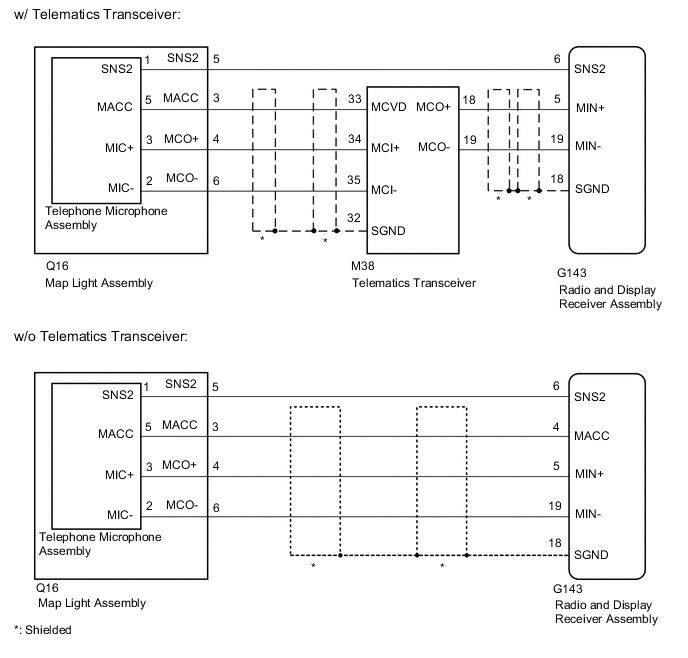
The radio and display receiver assembly and map light assembly (telephone microphone assembly) are connected to each other using the microphone connection detection signal lines.
This DTC is stored when a microphone connection detection signal line is disconnected.
| DTC No. | Detection Item | DTC Detection Condition | Trouble Area |
|---|---|---|---|
| B1579 | Voice Recognition Microphone Disconnected | Telephone microphone signal is lost. |
|
-
*: w/ Telematics Transceiver
WIRING DIAGRAM
CAUTION / NOTICE / HINT
Note
-
Check that the wire harness is properly installed and does not have any sharp bends, pinching or loose connections.
-
When replacing telematics transceiver, perform the vehicle contract setting.
PROCEDURE
-
CONFIRM MODEL
-
Choose the model to be inspected.
Model Model Proceed to w/o Telematics Transceiver A w/ Telematics Transceiver B
B 
CHECK HARNESS AND CONNECTOR (RADIO AND DISPLAY RECEIVER ASSEMBLY - MAP LIGHT ASSEMBLY) Click here
A 
-
-
CHECK HARNESS AND CONNECTOR (RADIO AND DISPLAY RECEIVER ASSEMBLY - MAP LIGHT ASSEMBLY)
-
Disconnect the G143 radio and display receiver assembly connector.
-
Disconnect the Q16 map light assembly connector.
-
Measure the resistance according to the value(s) in the table below.
Standard Resistance Tester Connection Condition Specified Condition G143-5 (MIN+) - Q16-4 (MCO+) Always Below 1 Ω G143-4 (MACC) - Q16-3 (MACC) Always Below 1 Ω G143-19 (MIN-) - Q16-6 (MCO-) Always Below 1 Ω G143-6 (SNS2) - Q16-5 (SNS2) Always Below 1 Ω G143-5 (MIN+) - Body ground Always 10 kΩ or higher G143-18 (SGND) - Body ground Always 10 kΩ or higher G143-4 (MACC) - Body ground Always 10 kΩ or higher G143-19 (MIN-) - Body ground Always 10 kΩ or higher G143-6 (SNS2) - Body ground Always 10 kΩ or higher Result Proceed to OK NG
NG 
REPAIR OR REPLACE HARNESS OR CONNECTOR
OK
-
-
INSPECT MAP LIGHT ASSEMBLY
-
Remove the map light assembly.
-
Remove the telephone microphone assembly.
-
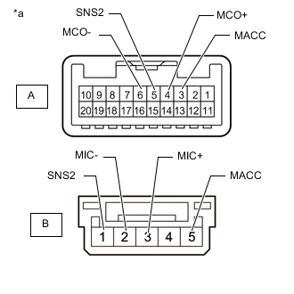
*a Component without harness connected
(Map Light Assembly)
Measure the resistance according to the value(s) in the table below.
Standard Resistance Tester Connection Condition Specified Condition A-3 (MACC) - B-5 (MACC) Always Below 1 Ω A-4 (MCO+) - B-3 (MIC+) Always Below 1 Ω A-5 (SNS2) - B-1 (SNS2) Always Below 1 Ω A-6 (MCO-) - B-2 (MIC-) Always Below 1 Ω A-3 (MACC) - A-4 (MCO+) Always 10 kΩ or higher A-3 (MACC) - A-5 (SNS2) Always 10 kΩ or higher A-3 (MACC) - A-6 (MCO-) Always 10 kΩ or higher A-4 (MCO+) - A-5 (SNS2) Always 10 kΩ or higher A-4 (MCO+) - A-6 (MCO-) Always 10 kΩ or higher A-5 (SNS2) - A-6 (MCO-) Always 10 kΩ or higher Result Proceed to OK NG
NG
REPLACE MAP LIGHT ASSEMBLY Click here
OK
-
-
REPLACE TELEPHONE MICROPHONE ASSEMBLY
-
Replace the telephone microphone assembly with a known good one.
-
Clear the DTCs.
Body Electrical > Navigation System > Clear DTCs -
Check for DTCs.
Body Electrical > Navigation System > Trouble CodesOK No DTCs are output. Result Proceed to OK NG
OK
END (TELEPHONE MICROPHONE ASSEMBLY IS DEFECTIVE)
NG
REPLACE RADIO AND DISPLAY RECEIVER ASSEMBLY Click here
-
-
CHECK HARNESS AND CONNECTOR (RADIO AND DISPLAY RECEIVER ASSEMBLY - MAP LIGHT ASSEMBLY)
-
Disconnect the G143 radio and display receiver assembly connector.
-
Disconnect the Q16 map light assembly connector.
-
Measure the resistance according to the value(s) in the table below.
Standard Resistance Tester Connection Condition Specified Condition G143-6 (SNS2) - Q16-5 (SNS2) Always Below 1 Ω Result Proceed to OK NG
NG
REPAIR OR REPLACE HARNESS OR CONNECTOR
OK
-
-
CHECK HARNESS AND CONNECTOR (RADIO AND DISPLAY RECEIVER ASSEMBLY - TELEMATICS TRANSCEIVER)
-
Disconnect the G143 radio and display receiver assembly connector.
-
Disconnect the M38 telematics transceiver connector.
-
Measure the resistance according to the value(s) in the table below.
Standard Resistance Tester Connection Condition Specified Condition G143-5 (MIN+) - M38-18 (MCO+) Always Below 1 Ω G143-19 (MIN-) - M38-19 (MCO-) Always Below 1 Ω G143-5 (MIN+) - Body ground Always 10 kΩ or higher G143-19 (MIN-) - Body ground Always 10 kΩ or higher G143-18 (SGND) - Body ground Always 10 kΩ or higher Result Proceed to OK NG
NG
REPAIR OR REPLACE HARNESS OR CONNECTOR
OK
-
-
CHECK HARNESS AND CONNECTOR (TELEMATICS TRANSCEIVER - MAP LIGHT ASSEMBLY)
-
Disconnect the M38 telematics transceiver connector.
-
Disconnect the Q16 map light assembly connector.
-
Measure the resistance according to the value(s) in the table below.
Standard Resistance Tester Connection Condition Specified Condition M38-33 (MCVD) - Q16-3 (MACC) Always Below 1 Ω M38-34 (MCI+) - Q16-4 (MCO+) Always Below 1 Ω M38-35 (MCI-) - Q16-6 (MCO-) Always Below 1 Ω M38-33 (MCVD) - Body ground Always 10 kΩ or higher M38-34 (MCI+) - Body ground Always 10 kΩ or higher M38-35 (MCI-) - Body ground Always 10 kΩ or higher M38-32 (SGND) - Body ground Always 10 kΩ or higher Result Proceed to OK NG
NG
REPAIR OR REPLACE HARNESS OR CONNECTOR
OK
-
-
INSPECT MAP LIGHT ASSEMBLY
-
Remove the map light assembly.
-
Remove the telephone microphone assembly.
-
*a Component without harness connected
(Map Light Assembly)
Measure the resistance according to the value(s) in the table below.
Standard Resistance Tester Connection Condition Specified Condition A-3 (MACC) - B-5 (MACC) Always Below 1 Ω A-4 (MCO+) - B-3 (MIC+) Always Below 1 Ω A-5 (SNS2) - B-1 (SNS2) Always Below 1 Ω A-6 (MCO-) - B-2 (MIC-) Always Below 1 Ω A-3 (MACC) - A-4 (MCO+) Always 10 kΩ or higher A-3 (MACC) - A-5 (SNS2) Always 10 kΩ or higher A-3 (MACC) - A-6 (MCO-) Always 10 kΩ or higher A-4 (MCO+) - A-5 (SNS2) Always 10 kΩ or higher A-4 (MCO+) - A-6 (MCO-) Always 10 kΩ or higher A-5 (SNS2) - A-6 (MCO-) Always 10 kΩ or higher Result Proceed to OK NG
NG
REPLACE MAP LIGHT ASSEMBLY Click here
OK
-
-
CHECK TELEMATICS TRANSCEIVER
-
Disconnect the Q16 map light assembly connector.
-
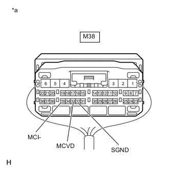
*a Component with harness connected
(Telematics Transceiver)
Measure the voltage according to the value(s) in the table below.
Standard Voltage Tester Connection Switch Condition Specified Condition M38-33 (MCVD) - Body ground Ignition switch ACC 4 to 6 V -
Measure the resistance according to the value(s) in the table below.
Standard Resistance Tester Connection Condition Specified Condition M38-32 (SGND) - Body ground Always Below 1 Ω M38-35 (MCI-) - Body ground Always Below 1 Ω Result Proceed to OK NG
NG
REPLACE TELEMATICS TRANSCEIVER Click here
OK
-
-
REPLACE TELEPHONE MICROPHONE ASSEMBLY
-
Replace the telephone microphone assembly with a known good one.
-
Clear the DTCs.
Body Electrical > Navigation System > Clear DTCs -
Check for DTCs.
Body Electrical > Navigation System > Trouble CodesOK No DTCs are output. Result Proceed to OK NG
OK
END (TELEPHONE MICROPHONE ASSEMBLY IS DEFECTIVE)
NG
REPLACE RADIO AND DISPLAY RECEIVER ASSEMBLY Click here
-