NAVIGATION SYSTEM(for Radio and Display Type), Diagnostic DTC:B15C0, B15C1
| DTC Code | DTC Name |
|---|---|
| B15C0 | GPS Antenna Connection Malfunction(short) |
| B15C1 | GPS Antenna Connection Malfunction(break) |
DESCRIPTION
These DTCs are stored when a malfunction occurs in the navigation antenna assembly.
| DTC No. | Detection Item | DTC Detection Condition | Trouble Area |
|---|---|---|---|
| B15C0 | GPS Antenna Connection Malfunction(short) | Navigation antenna error |
|
| B15C1 | GPS Antenna Connection Malfunction(break) | Error of the power source to the navigation antenna |
|
-
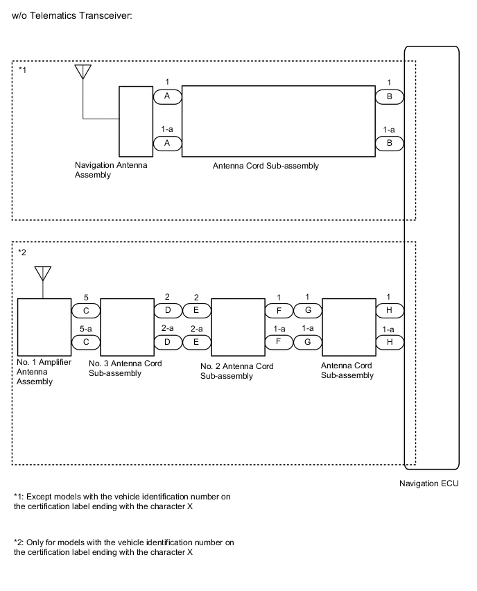
*1: Except models with the vehicle identification number on the certification label ending with the character X.
-
*2: Only for models with the vehicle identification number on the certification label ending with the character X.
-
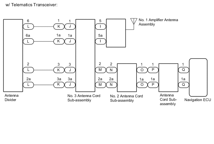
*3: w/ Telematics Transceiver
WIRING DIAGRAM
CAUTION / NOTICE / HINT
Note
Check that the wire harness is properly installed and does not have any sharp bends, pinching or loose connections.
PROCEDURE
-
CHECK CONNECTION OF NAVIGATION ANTENNA ASSEMBLY
-
Check if the navigation antenna assembly is securely connected to the antenna cord sub-assembly.
OK Navigation antenna assembly is securely connected. Result Proceed to OK NG
NG 
SECURELY CONNECT NAVIGATION ANTENNA ASSEMBLY
OK 
-
-
CHECK VEHICLE CONDITION
-
Check the vehicle condition.
Result Result Proceed to w/o Telematics Transceiver (Except models with the vehicle identification number on the certification label ending with the character X) A w/o Telematics Transceiver (Only for models with the vehicle identification number on the certification label ending with the character X) B w/ Telematics Transceiver C
B 
CHECK NO. 3 ANTENNA CORD SUB-ASSEMBLY Click here
C
CHECK NO. 3 ANTENNA CORD SUB-ASSEMBLY Click here
A
-
-
CHECK ANTENNA CORD SUB-ASSEMBLY
-
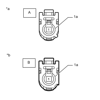
*a Front view of wire harness connector
(to Navigation Antenna Assembly)
*b Front view of wire harness connector
(to Navigation ECU)
Disconnect the antenna connector from the navigation ECU.
-
Disconnect the antenna connector from the navigation antenna assembly.
-
Measure the resistance according to the value(s) in the table below.
Standard Resistance Tester Connection Condition Specified Condition A-1 - B-1 Always Below 1 Ω A-1a - B-1a Always Below 1 Ω A-1 or B-1 - Body ground Always 10 kΩ or higher A-1a or B-1a - Body ground Always 10 kΩ or higher Result Proceed to OK NG
NG
REPLACE ANTENNA CORD SUB-ASSEMBLY Click here
OK
-
-
CHECK NAVIGATION ANTENNA ASSEMBLY
-
Replace the navigation antenna assembly with a known good one.
-
Clear the DTCs.
Body Electrical > Navigation System > Clear DTCs -
Check for DTCs.
Body Electrical > Navigation System > Trouble CodesOK No DTCs are output. Result Proceed to OK NG
OK
END (NAVIGATION ANTENNA ASSEMBLY IS DEFECTIVE)
NG
REPLACE NAVIGATION ECU Click here
-
-
CHECK NO. 3 ANTENNA CORD SUB-ASSEMBLY
-
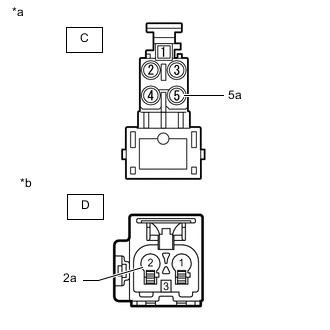
*a Front view of wire harness connector
(to No. 1 Amplifier Antenna Assembly)
*b Front view of wire harness connector
(to No. 2 Antenna Cord Sub-assembly)
Disconnect the antenna connector from the No. 1 amplifier antenna assembly.
-
Disconnect the antenna connector from the No. 2 antenna cord sub-assembly.
-
Measure the resistance according to the value(s) in the table below.
Standard Resistance Tester Connection Condition Specified Condition C-5 - D-2 Always Below 1 Ω C-5a - D-2a Always Below 1 Ω C-5 or D-2 - Body ground Always 10 kΩ or higher C-5a or D-2a - Body ground Always 10 kΩ or higher Result Proceed to OK NG
NG
REPLACE NO. 3 ANTENNA CORD SUB-ASSEMBLY Click here
OK
-
-
CHECK NO. 2 ANTENNA CORD SUB-ASSEMBLY
-
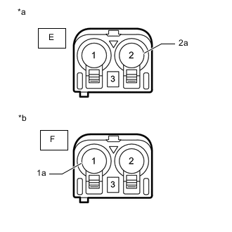
*a Front view of wire harness connector
(to No. 3 Antenna Cord Sub-assembly)
*b Front view of wire harness connector
(to Antenna Cord Sub-assembly)
Disconnect the antenna connector from the No. 3 antenna cord sub-assembly.
-
Disconnect the antenna connector from the antenna cord sub-assembly.
-
Measure the resistance according to the value(s) in the table below.
Standard Resistance Tester Connection Condition Specified Condition E-2 - F-1 Always Below 1 Ω E-2a - F-1a Always Below 1 Ω E-2 or F-1 - Body ground Always 10 kΩ or higher E-2a or F-1a - Body ground Always 10 kΩ or higher Result Proceed to OK NG
NG
REPLACE NO. 2 ANTENNA CORD SUB-ASSEMBLY Click here
OK
-
-
CHECK ANTENNA CORD SUB-ASSEMBLY
-
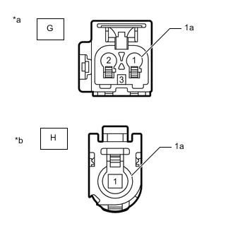
*a Front view of wire harness connector
(to No. 2 Antenna Cord Sub-assembly)
*b Front view of wire harness connector
(to Navigation ECU)
Disconnect the antenna connector from the No. 2 antenna cord sub-assembly.
-
Disconnect the antenna connector from the navigation ECU.
-
Measure the resistance according to the value(s) in the table below.
Standard Resistance Tester Connection Condition Specified Condition G-1 - H-1 Always Below 1 Ω G-1a - H-1a Always Below 1 Ω G-1 or H-1 - Body ground Always 10 kΩ or higher G-1a or H-1a - Body ground Always 10 kΩ or higher Result Proceed to OK NG
NG
REPLACE ANTENNA CORD SUB-ASSEMBLY Click here
OK
-
-
CHECK NO. 1 AMPLIFIER ANTENNA ASSEMBLY
-
Replace the No. 1 amplifier antenna assembly with a known good one.
-
Clear the DTCs.
Body Electrical > Navigation System > Clear DTCs -
Check for DTCs.
Body Electrical > Navigation System > Trouble CodesOK No DTCs are output. Result Proceed to OK NG
OK
END (NO. 1 AMPLIFIER ANTENNA ASSEMBLY IS DEFECTIVE)
NG
REPLACE NAVIGATION ECU Click here
-
-
CHECK NO. 3 ANTENNA CORD SUB-ASSEMBLY
-
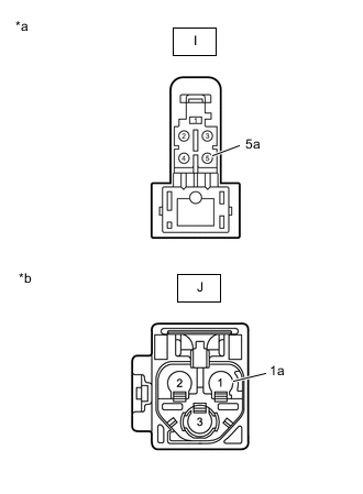
*a Front view of wire harness connector
(to No. 1 amplifier antenna assembly)
*b Front view of wire harness connector
(to wire haenass)
Disconnect the antenna connector from No. 1 amplifier antenna assembly.
-
Disconnect the antenna connector from the wire harness.
-
Measure the resistance according to the value(s) in the table below.
Standard Resistance Tester Connection Condition Specified Condition I-5 - J-1 Always Below 1 Ω I-5a - J-1a Always Below 1 Ω I-5 or J-1 - Body ground Always 10 kΩ or higher I-5a or J-1a - Body ground Always 10 kΩ or higher Result Proceed to OK NG
NG
REPLACE NO. 3 ANTENNA CORD SUB-ASSEMBLY Click here
OK
-
-
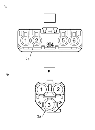
CHECK HARNESS AND CONNECTOR (NO. 3 ANTENNA CORD SUB-ASSEMBLY - ANTENNA DIVIDER)
-
Disconnect the antenna connector from the No. 3 antenna cord sub-assembly.
-
Disconnect the antenna connector from the antenna divider.
-
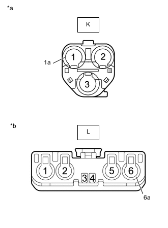
*a Front view of wire harness connector
(to No. 3 Antenna Cord Sub-assembly)
*a Front view of wire harness connector
(to Antenna Divider)
Measure the resistance according to the value(s) in the table below.
Standard Resistance Tester Connection Condition Specified Condition K-1 - L-6 Always Below 1 Ω K-1a - L-6a Always Below 1 Ω K-1 or L-6 - Body ground Always 10 kΩ or higher K-1a or L-6a - Body ground Always 10 kΩ or higher Result Proceed to OK NG
NG
REPAIR OR REPLACE HARNESS OR CONNECTOR
OK
-
-
INSPECT ANTENNA DIVIDER
-
Remove the antenna divider.
-
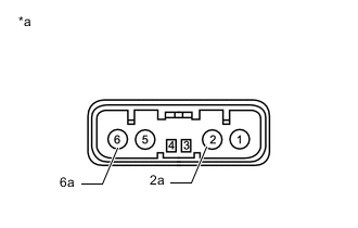
*a Component without harness connected
(Antenna Divider)
Measure the resistance according to the value(s) in the table below.
Standard Resistance Tester Connection Condition Specified Condition 6 - 2 Always 10 kΩ or higher 2 - 2a Always 243 to 267 Ω 6 - 6a Always 10 kΩ or higher Result Proceed to OK NG
NG
REPLACE ANTENNA DIVIDER Click here
OK
-
-
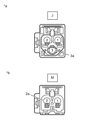
CHECK HARNESS AND CONNECTOR (ANTENNA DIVIDER - NO. 3 ANTENNA CORD SUB-ASSEMBLY)
-
Disconnect the antenna connector from the No. 3 antenna cord sub-assembly.
-
Disconnect the antenna connector from the antenna divider.
-
*a Front view of wire harness connector
(to Antenna Divider)
*a Front view of wire harness connector
(to No. 3 Antenna Cord Sub-assembly)
Measure the resistance according to the value(s) in the table below.
Standard Resistance Tester Connection Condition Specified Condition L-2 - K-3 Always Below 1 Ω L-2a - K-3a Always Below 1 Ω L-2 or K-3 - Body ground Always 10 kΩ or higher L-2a or K-3a - Body ground Always 10 kΩ or higher Result Proceed to OK NG
NG
REPAIR OR REPLACE HARNESS OR CONNECTOR
OK
-
-
CHECK NO. 3 ANTENNA CORD SUB-ASSEMBLY
-
*a Front view of wire harness connector
(to wire harness)
*b Front view of wire harness connector
(to No. 2 Antenna Cord Sub-assembly)
Disconnect the antenna connector from the wire harness.
-
Disconnect the antenna connector from the No. 2 antenna cord sub-assembly.
-
Measure the resistance according to the value(s) in the table below.
Standard Resistance Tester Connection Condition Specified Condition J-3 - M-2 Always Below 1 Ω J-3a - M-2a Always Below 1 Ω J-3 or M-2 - Body ground Always 10 kΩ or higher J-3a or M-2a - Body ground Always 10 kΩ or higher Result Proceed to OK NG
NG
REPLACE NO. 3 ANTENNA CORD SUB-ASSEMBLY Click here
OK
-
-
CHECK NO. 2 ANTENNA CORD SUB-ASSEMBLY
-
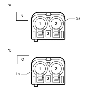
*a Front view of wire harness connector
(to No. 3 Antenna Cord Sub-assembly)
*b Front view of wire harness connector
(to Antenna Cord Sub-assembly)
Disconnect the antenna connector from the No. 3 antenna cord sub-assembly.
-
Disconnect the antenna connector from the antenna cord sub-assembly.
-
Measure the resistance according to the value(s) in the table below.
Standard Resistance Tester Connection Condition Specified Condition N-2 - O-1 Always Below 1 Ω N-2a - O-1a Always Below 1 Ω N-2 or O-1 - Body ground Always 10 kΩ or higher N-2a or O-1a - Body ground Always 10 kΩ or higher Result Proceed to OK NG
NG
REPLACE NO. 2 ANTENNA CORD SUB-ASSEMBLY Click here
OK
-
-
CHECK ANTENNA CORD SUB-ASSEMBLY
-

*a Front view of wire harness connector
(to No. 2 Antenna Cord Sub-assembly)
*b Front view of wire harness connector
(to Navigation ECU)
Disconnect the antenna connector from the No. 2 antenna cord sub-assembly.
-
Disconnect the antenna connector from the navigation ECU.
-
Measure the resistance according to the value(s) in the table below.
Standard Resistance Tester Connection Condition Specified Condition P-1 - Q-1 Always Below 1 Ω P-1a - Q-1a Always Below 1 Ω P-1 or Q-1 - Body ground Always 10 kΩ or higher P-1a or Q-1a - Body ground Always 10 kΩ or higher Result Proceed to OK NG
NG
REPLACE ANTENNA CORD SUB-ASSEMBLY Click here
OK
-
-
CHECK NO. 1 AMPLIFIER ANTENNA ASSEMBLY
-
Replace the No. 1 amplifier antenna assembly with a known good one.
-
Clear the DTCs.
Body Electrical > Navigation System > Clear DTCs -
Check for DTCs.
Body Electrical > Navigation System > Trouble CodesOK No DTCs are output. Result Proceed to OK NG
OK
END (NO. 1 AMPLIFIER ANTENNA ASSEMBLY IS DEFECTIVE)
NG
-
-
CHECK ANTENNA DIVIDER
-
Replace the antenna divider with a new or known good one.
-
Clear the DTCs.
Body Electrical > Navigation System > Clear DTCs -
Check for DTCs.
Body Electrical > Navigation System > Trouble CodesOK No DTCs are output. Result Proceed to OK NG
OK
END (ANTENNA DIVIDER IS DEFECTIVE)
NG
REPLACE NAVIGATION ECU Click here
-