NAVIGATION SYSTEM(for Radio and Display Type), Diagnostic DTC:B15C3
| DTC Code | DTC Name |
|---|---|
| B15C3 | Speaker Output Short |
DESCRIPTION
This DTC is stored when a malfunction occurs in the speakers.
| DTC No. | Detection Item | DTC Detection Condition | Trouble Area |
|---|---|---|---|
| B15C3 | Speaker Output Short | A short is detected in the speaker output circuit. |
|
-
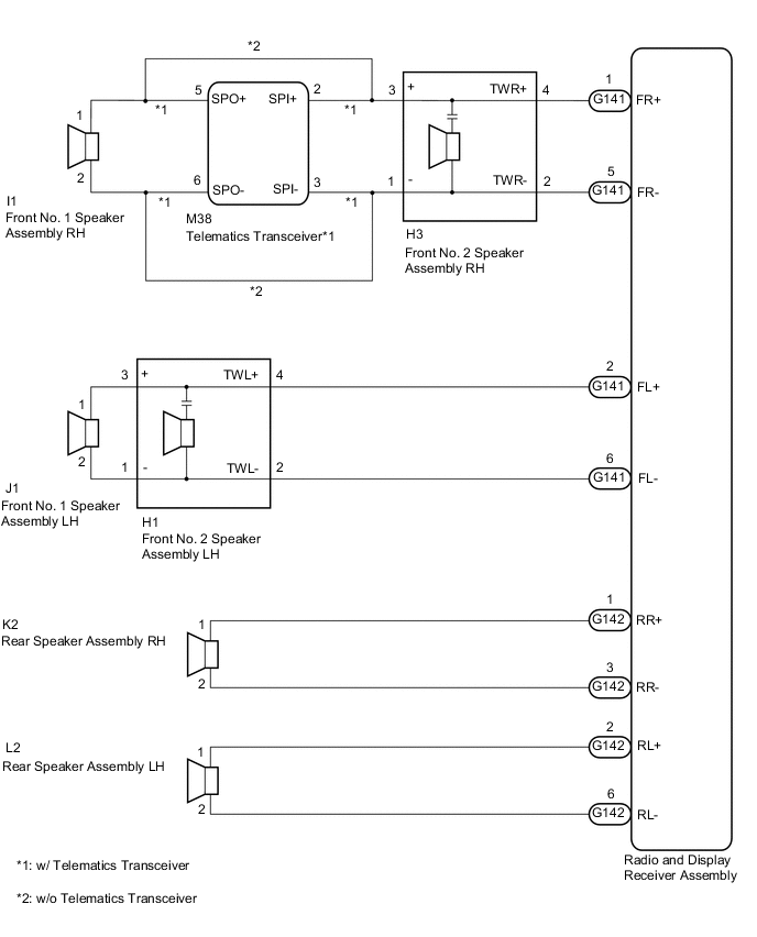
*: w/ Telematics Transceiver
WIRING DIAGRAM
CAUTION / NOTICE / HINT
Note
-
Check that the wire harness is properly installed and does not have any sharp bends, pinching or loose connections.
-
When replacing telematics transceiver, perform the vehicle contract setting.
PROCEDURE
-
CHECK FOR DTC
-
Clear the DTCs.
Body Electrical > Navigation System > Clear DTCs -
Check for DTCs.
Body Electrical > Navigation System > Trouble CodesOK No DTCs are output. Result Proceed to OK NG
OK 
USE SIMULATION METHOD TO CHECK Click here
NG 
-
-
CHECK VEHICLE CONDITION
-
Check the vehicle condition.
Result Result Proceed to w/ Telematics Transceiver A w/o Telematics Transceiver B
B 
CHECK HARNESS AND CONNECTOR (SPEAKER CIRCUIT) Click here
A
-
-
CHECK HARNESS AND CONNECTOR (SPEAKER CIRCUIT)
-
*1: for LH Side
-
*2: for RH Side
-
Disconnect the G141 and G142 radio and display receiver assembly connectors.
-
Disconnect the J1*1 and/or I1*2 front No. 1 speaker assembly connector.
-
Disconnect the H1*1 and/or H3*2 front No. 2 speaker assembly connector.
-
Disconnect the L2*1 and/or K2*2 rear speaker assembly connector.
-
Disconnect the M38 telematics transceiver connector.
-
Measure the resistance according to the value(s) in the table below.
Standard Resistance for LH Side Tester Connection Condition Specified Condition G141-2 (FL+) - H1-4 (TWL+) Always Below 1 Ω G141-6 (FL-) - H1-2 (TWL-) Always Below 1 Ω H1-3 (+) - J1-1 Always Below 1 Ω H1-1 (-) - J1-2 Always Below 1 Ω G142-2 (RL+) - L2-1 Always Below 1 Ω G142-6 (RL-) - L2-2 Always Below 1 Ω G141-2 (FL+) - Body ground Always 10 kΩ or higher G141-6 (FL-) - Body ground Always 10 kΩ or higher G142-2 (RL+) - Body ground Always 10 kΩ or higher G142-6 (RL-) - Body ground Always 10 kΩ or higher H1-3 (+) - Body ground Always 10 kΩ or higher H1-1 (-) - Body ground Always 10 kΩ or higher for RH Side Tester Connection Condition Specified Condition G141-1 (FR+) - H3-4 (TWR+) Always Below 1 Ω G141-5 (FR-) - H3-2 (TWR-) Always Below 1 Ω H3-3 (+) - M38-2 (SPI+) Always Below 1 Ω H3-1 (-) - M38-3 (SPI-) Always Below 1 Ω M38-5 (SPO+) - I1-1 Always Below 1 Ω M38-6 (SPO-) - I1-2 Always Below 1 Ω G142-1 (RR+) - K2-1 Always Below 1 Ω G142-3 (RR-) - K2-2 Always Below 1 Ω G141-1 (FR+) - Body ground Always 10 kΩ or higher G141-5 (FR-) - Body ground Always 10 kΩ or higher M38-5 (SPO+) - Body ground Always 10 kΩ or higher M38-6 (SPO-) - Body ground Always 10 kΩ or higher G142-1 (RR+) - Body ground Always 10 kΩ or higher G142-3 (RR-) - Body ground Always 10 kΩ or higher H3-3 (+) - Body ground Always 10 kΩ or higher H3-1 (-) - Body ground Always 10 kΩ or higher Result Proceed to OK NG
NG
REPAIR OR REPLACE HARNESS OR CONNECTOR
OK
-
-
INSPECT TELEMATICS TRANSCEIVER
-
Remove the telematics transceiver.
-
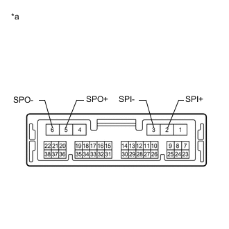
*a Component without harness connected
(Telematics Transceiver)
Measure the resistance according to the value(s) in the table below.
Standard Resistance Tester Connection Condition Specified Condition 2 (SPI+) - 5 (SPO+) Always Below 1 Ω 3 (SPI-) - 6 (SPO-) Always Below 1 Ω 2 (SPI+) - 3 (SPI-) Always 10 kΩ or higher 5 (SPO+) - 6 (SPO-) Always 10 kΩ or higher 2 (SPI+) or 5 (SPO+) - Body ground Always 10 kΩ or higher 3 (SPI-) or 6 (SPO-) - Body ground Always 10 kΩ or higher Result Proceed to OK NG
OK
GO TO STEP 6 Click here
NG
REPLACE TELEMATICS TRANSCEIVER Click here
-
-
CHECK HARNESS AND CONNECTOR (SPEAKER CIRCUIT)
-
*1: for LH Side
-
*2: for RH Side
-
Disconnect the G141 and G142 radio and display receiver assembly connectors.
-
Disconnect the J1*1 and/or I1*2 front No. 1 speaker assembly connector.
-
Disconnect the H1*1 and/or H3*2 front No. 2 speaker assembly connector.
-
Disconnect the L2*1 and/or K2*2 rear speaker assembly connector.
-
Measure the resistance according to the value(s) in the table below.
Standard Resistance for LH Side Tester Connection Condition Specified Condition G141-2 (FL+) - H1-4 (TWL+) Always Below 1 Ω G141-6 (FL-) - H1-2 (TWL-) Always Below 1 Ω H1-3 (+) - J1-1 Always Below 1 Ω H1-1 (-) - J1-2 Always Below 1 Ω G142-2 (RL+) - L2-1 Always Below 1 Ω G142-6 (RL-) - L2-2 Always Below 1 Ω G141-2 (FL+) - Body ground Always 10 kΩ or higher G141-6 (FL-) - Body ground Always 10 kΩ or higher G142-2 (RL+) - Body ground Always 10 kΩ or higher G142-6 (RL-) - Body ground Always 10 kΩ or higher H1-3 (+) - Body ground Always 10 kΩ or higher H1-1 (-) - Body ground Always 10 kΩ or higher for RH Side Tester Connection Condition Specified Condition G141-1 (FR+) - H3-4 (TWR+) Always Below 1 Ω G141-5 (FR-) - H3-2 (TWR-) Always Below 1 Ω H3-3 (+) - I1-1 Always Below 1 Ω H3-1 (-) - I1-2 Always Below 1 Ω G142-1 (RR+) - K2-1 Always Below 1 Ω G142-3 (RR-) - K2-2 Always Below 1 Ω G141-1 (FR+) - Body ground Always 10 kΩ or higher G141-5 (FR-) - Body ground Always 10 kΩ or higher G142-1 (RR+) - Body ground Always 10 kΩ or higher G142-3 (RR-) - Body ground Always 10 kΩ or higher H3-3 (+) - Body ground Always 10 kΩ or higher H3-1 (-) - Body ground Always 10 kΩ or higher Result Proceed to OK NG
NG
REPAIR OR REPLACE HARNESS OR CONNECTOR
OK
-
-
INSPECT FRONT NO. 1 SPEAKER ASSEMBLY
-
Remove the front No. 1 speaker assembly connector.
-
Inspect the front No. 1 speaker assembly.
Result Proceed to OK NG
NG
REPLACE FRONT NO. 1 SPEAKER ASSEMBLY Click here
OK
-
-
CHECK FRONT NO. 2 SPEAKER ASSEMBLY
-
Replace the front No. 2 speaker assembly with a known good one.
-
Clear the DTCs.
Body Electrical > Navigation System > Clear DTCs -
Check for DTCs and check if the same DTCs is output.
Body Electrical > Navigation System > Trouble CodesNote
-
Connect all the connectors that were disconnected to the front No. 2 speaker assemblies.
-
Perform the above inspection on both LH and RH sides.
OK No DTCs are output. Result Proceed to OK NG -
OK
END (FRONT NO. 2 SPEAKER ASSEMBLY IS DEFECTIVE)
NG
-
-
INSPECT REAR SPEAKER ASSEMBLY
-
Remove the rear speaker assembly connector.
-
Inspect the rear speaker assembly.
Result Proceed to OK NG
OK
REPLACE RADIO AND DISPLAY RECEIVER ASSEMBLY Click here
NG
REPLACE REAR SPEAKER ASSEMBLY Click here
-