AUDIO AND VISUAL SYSTEM(for Radio and Display Type) Radio Receiver Power Source Circuit
DESCRIPTION
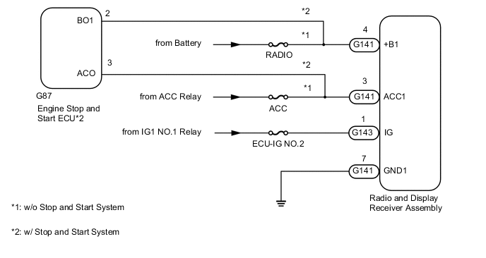
This is the power source circuit to operate the radio and display receiver assembly.
WIRING DIAGRAM
CAUTION / NOTICE / HINT
Note
Inspect the fuses for circuits related to this system before performing the following inspection procedure.
PROCEDURE
-
CONFIRM MODEL
-
Choose the model to be inspected.
Result Proceed to w/o Stop and Start System w/ Stop and Start System
w/ Stop and Start System 
CHECK HARNESS AND CONNECTOR (RADIO AND DISPLAY RECEIVER ASSEMBLY - ENGINE STOP AND START ECU) Click here
w/o Stop and Start System 
-
-
CHECK HARNESS AND CONNECTOR (RADIO AND DISPLAY RECEIVER ASSEMBLY - BATTERY AND BODY GROUND)
-
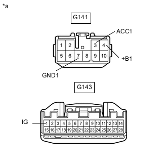
*a Front view of wire harness connector
(to Radio and Display Receiver Assembly)
Disconnect the radio and display receiver assembly connectors.
-
Measure the resistance according to the value(s) in the table below.
Standard Resistance Tester Connection Condition Specified Condition G141-7 (GND1) - Body ground Always Below 1 Ω -
Measure the voltage according to the value(s) in the table below.
Standard Voltage w/o Stop and Start System Tester Connection Condition Specified Condition G141-4 (+B1) - G141-7 (GND1) Always 11 to 14 V G141-3 (ACC1) - G141-7 (GND1) Ignition switch ACC 11 to 14 V Ignition switch off Below 1 V G143-1 (IG) - G141-7 (GND1) Ignition switch ON 11 to 14 V Ignition switch off Below 1 V Standard Voltage w/ Stop and Start System Tester Connection Condition Specified Condition G141-4 (+B1) - G141-7 (GND1) Always 10.5 to 14 V G141-3 (ACC1) - G141-7 (GND1) Ignition switch ACC 10.5 to 14 V Ignition switch off Below 1 V G143-1 (IG) - G141-7 (GND1) Ignition switch ON 11 to 14 V Ignition switch off Below 1 V Result Proceed to OK NG
OK 
PROCEED TO NEXT SUSPECTED AREA SHOWN IN PROBLEM SYMPTOMS TABLE Click here
NG
REPAIR OR REPLACE HARNESS OR CONNECTOR
-
-
CHECK HARNESS AND CONNECTOR (RADIO AND DISPLAY RECEIVER ASSEMBLY - ENGINE STOP AND START ECU)
-
Disconnect the G141 radio and display receiver assembly connector.
-
Disconnect the G87 engine stop and start ECU connector.
-
Measure the resistance according to the value(s) in the table below.
Standard Resistance Tester Connection Condition Specified Condition G141-4 (+B1) - G87-2 (BO1) Always Below 1 Ω G141-3 (ACC1) - G87-3 (ACO) Always Below 1 Ω G141-4 (+B1) - Body ground Always 10 kΩ or higher G141-3 (ACC1) - Body ground Always 10 kΩ or higher Result Proceed to OK NG
NG
REPAIR OR REPLACE HARNESS OR CONNECTOR
OK
-
-
CHECK ENGINE STOP AND START ECU
-
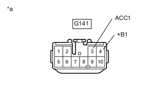
*a Front view of wire harness connector
(to Radio and Display Receiver Assembly)
Disconnect the radio and display receiver assembly connector.
-
Reconnect the G87 engine stop and start ECU connector.
-
Measure the voltage according to the value(s) in the table below.
Standard Voltage Tester Connection Condition Specified Condition G141-4 (+B1) - Body ground Always 10.5 to 14 V G141-3 (ACC1) - Body ground Ignition switch ACC 10.5 to 14 V Ignition switch off Below 1 V Result Proceed to OK NG
NG
GO TO STOP AND START SYSTEM Click here
OK
-
-
CHECK HARNESS AND CONNECTOR (RADIO AND DISPLAY RECEIVER ASSEMBLY - BATTERY AND BODY GROUND)
-
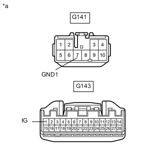
*a Front view of wire harness connector
(to Radio and Display Receiver Assembly)
Disconnect the radio and display receiver assembly connectors.
-
Measure the resistance according to the value(s) in the table below.
Standard Resistance Tester Connection Condition Specified Condition G141-7 (GND1) - Body ground Always Below 1 Ω -
Measure the voltage according to the value(s) in the table below.
Standard Voltage Tester Connection Switch Condition Specified Condition G143-1 (IG) - G141-7 (GND1) Ignition switch ON 11 to 14 V Ignition switch off Below 1 V Result Proceed to OK NG
OK
PROCEED TO NEXT SUSPECTED AREA SHOWN IN PROBLEM SYMPTOMS TABLE Click here
NG
REPAIR OR REPLACE HARNESS OR CONNECTOR
-