AUDIO AND VISUAL SYSTEM(for Radio and Display Type), Diagnostic DTC:B15D8
| DTC Code | DTC Name |
|---|---|
| B15D8 | Monitor Disconnected |
DESCRIPTION
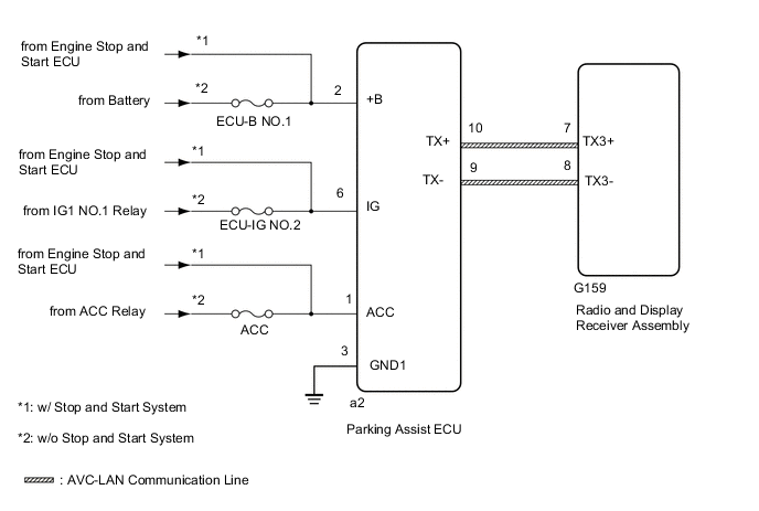
The parking assist ECU and radio and display receiver assembly are connected by an AVC-LAN communication line. When an AVC-LAN communication error occurs between the radio and display receiver assembly and parking assist ECU, these DTCs will be stored.
| DTC No. | Detection Item | DTC Detection Condition | Trouble Area |
|---|---|---|---|
| B15D8 | Monitor Disconnected | A device that is listed in the AVC-LAN connected device record of the master unit is missing. |
|
Tech Tips
-
Even if no fault is present, this DTC may be stored depending on the battery condition.
-
The radio and display receiver assembly is the master unit.
WIRING DIAGRAM
CAUTION / NOTICE / HINT
Note
-
Inspect the fuses for circuits related to this system before performing the following procedure.
-
Check that the wire harness is properly installed and does not have any sharp bends, pinching or loose connections
PROCEDURE
-
CLEAR DTC
-
Clear the DTCs.
Body Electrical > Navigation System > Clear DTCsResult Proceed to NEXT
NEXT 
-
-
CHECK FOR DTC
-
Recheck for DTCs and check if the same DTC is output again.
Body Electrical > Navigation System > Trouble CodesOK No DTCs are output. Result Proceed to OK NG
OK 
USE SIMULATION METHOD TO CHECK Click here
NG
-
-
CHECK HARNESS AND CONNECTOR (PARKING ASSIST ECU - BATTERY AND BODY GROUND)
-
Disconnect the parking assist ECU connector.
-
Measure the resistance according to the value(s) in the table below.
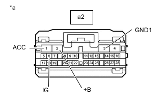
Standard Resistance Tester Connection Condition Specified Condition a2-3 (GND1) - Body ground Always Below 1 Ω -
Measure the voltage according to the value(s) in the table below.
Standard Voltage Tester Connection Condition Specified Condition a2-2 (+B) - a2-3 (GND1) Always 11 to 14 V*1
10.5 to 16 V*2
a2-6 (IG) - a2-3 (GND1) Ignition switch ON 11 to 14 V*1
10.5 to 16 V*2
a2-1 (ACC) - a2-3 (GND1) Ignition switch ACC 11 to 14 V*1
10.5 to 16 V*2
-
*1: w/o Stop and Start System
-
*2: w/ Stop and Start System
Result Proceed to OK NG -
NG
REPAIR OR REPLACE HARNESS OR CONNECTOR
OK
-
-
INSPECT RADIO AND DISPLAY RECEIVER ASSEMBLY
-
Remove the radio and display receiver assembly.
-
Measure the resistance according to the value(s) in the table below.
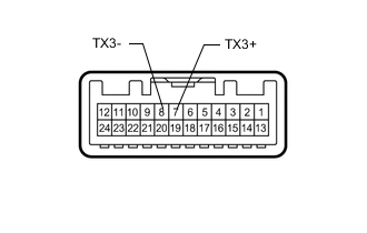
Standard Resistance Tester Connection Condition Specified Condition 7 (TX3+) - 8 (TX3-) Always 60 to 80 Ω Result Proceed to OK NG
NG
REPLACE RADIO AND DISPLAY RECEIVER ASSEMBLY Click here
OK
-
-
CHECK HARNESS AND CONNECTOR (RADIO AND DISPLAY RECEIVER ASSEMBLY - PARKING ASSIST ECU)
-
Disconnect the G159 radio and display receiver assembly connector.
-
Disconnect the a2 parking assist ECU connector.
-
Measure the resistance according to the value(s) in the table below.
Standard Resistance Tester Connection Condition Specified Condition G159-7 (TX3+) - a2-10 (TX+) Always Below 1 Ω G159-8 (TX3-) - a2-9 (TX-) Always Below 1 Ω G159-7 (TX3+) - Body ground Always 10 kΩ or higher G159-8 (TX3-) - Body ground Always 10 kΩ or higher Result Proceed to OK NG
NG
REPAIR OR REPLACE HARNESS OR CONNECTOR
OK
-
-
CHECK PARKING ASSIST ECU
-
Replace the parking assist ECU with a new or known good one.
Result Proceed to NEXT
NEXT
-
-
CLEAR DTC
-
Clear the DTCs.
Body Electrical > Navigation System > Clear DTCsResult Proceed to NEXT
NEXT
-
-
CHECK FOR DTC
-
Recheck for DTCs and check if the same DTC is output again.
Body Electrical > Navigation System > Trouble CodesOK No DTCs are output. Result Proceed to OK NG
OK
END (PARKING ASSIST ECU IS DEFECTIVE)
NG
REPLACE RADIO AND DISPLAY RECEIVER ASSEMBLY Click here
-