AUDIO AND VISUAL SYSTEM(for Radio Receiver Type) Microphone Circuit between Microphone and Radio Receiver
DESCRIPTION
-
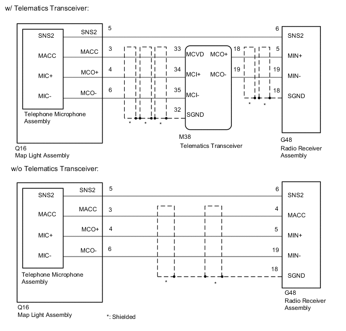
The radio receiver assembly and telephone microphone assembly are connected to each other using the microphone connection detection signal lines.
Using this circuit, the radio receiver assembly sends power to the telephone microphone assembly, and the telephone microphone assembly sends microphone signals to the radio receiver assembly.
w/o Telematics Transceiver:
-
The radio receiver assembly and telephone microphone assembly are connected to each other using the microphone connection detection signal lines.
Using this circuit, the telematics transceiver sends power to the telephone microphone assembly, and the telephone microphone assembly sends microphone signals to the radio receiver assembly via the telematics transceiver.
w/ Telematics Transceiver:
WIRING DIAGRAM
CAUTION / NOTICE / HINT
Note
Depending on the parts that are replaced during vehicle inspection or maintenance, performing initialization, registration or calibration may be needed. Refer to Precaution for Audio and Visual System.
PROCEDURE
-
CONFIRM MODEL
-
Choose the model to be inspected.
Model Model Proceed to w/o Telematics Transceiver A w/ Telematics Transceiver B
B 
CHECK HARNESS AND CONNECTOR (RADIO RECEIVER ASSEMBLY - MAP LIGHT ASSEMBLY) Click here
A 
-
-
CHECK HARNESS AND CONNECTOR (RADIO RECEIVER ASSEMBLY - MAP LIGHT ASSEMBLY)
-
Disconnect the G48 radio receiver assembly connector.
-
Disconnect the Q16 map light assembly (telephone microphone assembly) connector.
-
Measure the resistance according to the value(s) in the table below.
Standard Resistance Tester Connection Condition Specified Condition G48-6 (SNS2) - Q16-5 (SNS2) Always Below 1 Ω G48-4 (MACC) - Q16-3 (MACC) Always Below 1 Ω G48-5 (MIN+) - Q16-4 (MCO+) Always Below 1 Ω G48-19 (MIN-) - Q16-6 (MCO-) Always Below 1 Ω G48-6 (SNS2) - Body ground Always 10 kΩ or higher G48-4 (MACC) - Body ground Always 10 kΩ or higher G48-5 (MIN+) - Body ground Always 10 kΩ or higher G48-19 (MIN-) - Body ground Always 10 kΩ or higher G48-18 (SGND) - Body ground Always 10 kΩ or higher Result Proceed to OK NG
NG 
REPAIR OR REPLACE HARNESS OR CONNECTOR
OK
-
-
INSPECT MAP LIGHT ASSEMBLY
-
Remove the map light assembly.
-
Remove the telephone microphone assembly.
-
Measure the resistance according to the value(s) in the table below.
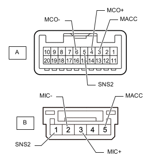
Standard Resistance Tester Connection Condition Specified Condition A-3 (MACC) - B-5 (MACC) Always Below 1 Ω A-4 (MCO+) - B-3 (MIC+) Always Below 1 Ω A-5 (SNS2) - B-1 (SNS2) Always Below 1 Ω A-6 (MCO-) - B-2 (MIC-) Always Below 1 Ω A-3 (MACC) - A-4 (MCO+) Always 10 kΩ or higher A-3 (MACC) - A-5 (SNS2) Always 10 kΩ or higher A-3 (MACC) - A-6 (MCO-) Always 10 kΩ or higher A-4 (MCO+) - A-5 (SNS2) Always 10 kΩ or higher A-4 (MCO+) - A-6 (MCO-) Always 10 kΩ or higher A-5 (SNS2) - A-6 (MCO-) Always 10 kΩ or higher Result Proceed to OK NG
NG
REPLACE MAP LIGHT ASSEMBLY Click here
OK
-
-
CHECK TELEPHONE MICROPHONE ASSEMBLY
-
Replace the telephone microphone assembly with a new or known good one and check that the malfunction disappears.
OK Malfunction disappears. Result Proceed to OK NG
OK
END (TELEPHONE MICROPHONE ASSEMBLY IS DEFECTIVE)
NG
REPLACE RADIO RECEIVER ASSEMBLY Click here
-
-
CHECK HARNESS AND CONNECTOR (RADIO RECEIVER ASSEMBLY - MAP LIGHT ASSEMBLY)
-
Disconnect the G48 radio receiver assembly connector.
-
Disconnect the Q16 map light assembly (telephone micro phone assembly) connector.
-
Measure the resistance according to the value(s) in the table below.
Standard Resistance Tester Connection Condition Specified Condition G48-6 (SNS2) - Q16-5 (SNS2) Always Below 1 Ω Result Proceed to OK NG
NG
REPAIR OR REPLACE HARNESS OR CONNECTOR
OK
-
-
CHECK HARNESS AND CONNECTOR (RADIO RECEIVER ASSEMBLY - TELEMATICS TRANSCEIVER)
-
Disconnect the G48 radio receiver assembly connector.
-
Disconnect the M38 telematics transceiver connector.
-
Measure the resistance according to the value(s) in the table below.
Standard Resistance Tester Connection Condition Specified Condition G48-5 (MIN+) - M38-18 (MCO+) Always Below 1 Ω G48-19 (MIN-) - M38-19 (MCO-) Always Below 1 Ω G48-5 (MIN+) - Body ground Always 10 kΩ or higher G48-19 (MIN-) - Body ground Always 10 kΩ or higher G48-18 (SGND) - Body ground Always 10 kΩ or higher Result Proceed to OK NG
NG
REPAIR OR REPLACE HARNESS OR CONNECTOR
OK
-
-
CHECK HARNESS AND CONNECTOR (TELEMATICS TRANSCEIVER - MAP LIGHT ASSEMBLY)
-
Disconnect the M38 telematics transceiver connector.
-
Disconnect the Q16 map light assembly connector.
-
Measure the resistance according to the value(s) in the table below.
Standard Resistance Tester Connection Condition Specified Condition M38-33 (MCVD) - Q16-3 (MACC) Always Below 1 Ω M38-34 (MCI+) - Q16-4 (MCO+) Always Below 1 Ω M38-35 (MCI-) - Q16-6 (MCO-) Always Below 1 Ω M38-33 (MCVD) - Body ground Always 10 kΩ or higher M38-34 (MCI+) - Body ground Always 10 kΩ or higher M38-35 (MCI-) - Body ground Always 10 kΩ or higher M38-32 (SGND) - Body ground Always 10 kΩ or higher Result Proceed to OK NG
NG
REPAIR OR REPLACE HARNESS OR CONNECTOR
OK
-
-
INSPECT MAP LIGHT ASSEMBLY
-
Remove the map light assembly.
-
Remove the telephone microphone assembly.
-
Measure the resistance according to the value(s) in the table below.
Standard Resistance Tester Connection Condition Specified Condition A-3 (MACC) - B-5 (MACC) Always Below 1 Ω A-4 (MCO+) - B-3 (MIC+) Always Below 1 Ω A-5 (SNS2) - B-1 (SNS2) Always Below 1 Ω A-6 (MCO-) - B-2 (MIC-) Always Below 1 Ω A-3 (MACC) - A-4 (MCO+) Always 10 kΩ or higher A-3 (MACC) - A-5 (SNS2) Always 10 kΩ or higher A-3 (MACC) - A-6 (MCO-) Always 10 kΩ or higher A-4 (MCO+) - A-5 (SNS2) Always 10 kΩ or higher A-4 (MCO+) - A-6 (MCO-) Always 10 kΩ or higher A-5 (SNS2) - A-6 (MCO-) Always 10 kΩ or higher Result Proceed to OK NG
NG
REPLACE MAP LIGHT ASSEMBLY Click here
OK
-
-
CHECK TELEMATICS TRANSCEIVER
-
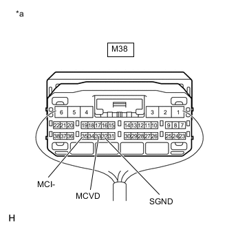
*a Component with harness connected
(Telematics Transceiver)
Disconnect the Q16 map light assembly connector.
-
Measure the voltage according to the value(s) in the table below.
Standard Voltage Tester Connection Switch Condition Specified Condition M38-33 (MCVD) - Body ground Ignition switch ACC 4 to 6 V -
Measure the resistance according to the value(s) in the table below.
Standard Resistance Tester Connection Condition Specified Condition M38-32 (SGND) - Body ground Always Below 1 Ω M38-35 (MCI-) - Body ground Always Below 1 Ω Result Proceed to OK NG
NG
REPLACE TELEMATICS TRANSCEIVER Click here
OK
-
-
CHECK TELEPHONE MICROPHONE ASSEMBLY
-
Replace the telephone microphone assembly with a new or known good one and check that the malfunction disappears.
OK Malfunction disappears. Result Proceed to OK NG
OK
END (TELEPHONE MICROPHONE ASSEMBLY IS DEFECTIVE)
NG
REPLACE RADIO RECEIVER ASSEMBLY Click here
-