STEERING GEAR INSTALLATION

CAUTION / NOTICE / HINT
Tech Tips
-
Use the same procedure for RHD and LHD vehicles.
-
The procedure listed below is for LHD vehicles.
PROCEDURE
-
INSTALL STEERING GEAR ASSEMBLY
-
Install the steering gear assembly to the front suspension crossmember with the 2 bolts and 2 nuts.
- Torque:
- 110 N*m { 1122 kgf*cm, 81 ft.*lbf }
Note
-
Make sure to tighten the bolts starting from the left side of the vehicle.
-
Because the nut has its own stopper, do not turn the nut. Tighten the bolt with the nut fixed in place.
-
-
INSTALL STEERING INTERMEDIATE SHAFT
-
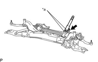
*a Matchmark Align the matchmarks and install the steering intermediate shaft to the steering gear assembly.
-
Install the bolt.
- Torque:
- 35.3 N*m { 360 kgf*cm, 26 ft.*lbf }
-
-
INSTALL NO. 1 STEERING COLUMN HOLE COVER SUB-ASSEMBLY
-
Align the round hole in the No. 1 steering column hole cover assembly with the protrusion of the steering gear assembly and install the cover.
-
Install a new clamp.
-
-
INSTALL FRONT SUSPENSION CROSSMEMBER SUB-ASSEMBLY
-
INSTALL STEERING GEAR HEAT INSULATOR (for ZR Series Engine RHD)
-
Install the heat insulator and bolt to the steering gear.
- Torque:
- 8.0 N*m { 82 kgf*cm, 71 in.*lbf }
-
-
INSTALL FRONT SUSPENSION MEMBER REAR BRACE LH
-
INSTALL FRONT SUSPENSION MEMBER REAR BRACE RH
Tech Tips
Use the same procedure described for the LH side.
-
INSTALL LOWER ENGINE FRONT MOUNTING BRACKET REINFORCEMENT (for 3ZR-FE (2WD) and 1AD-FTV)
-
INSTALL FRONT SUSPENSION MEMBER REINFORCEMENT LH
-
INSTALL FRONT SUSPENSION MEMBER REINFORCEMENT RH
Tech Tips
Use the same procedure described for the LH side.
-
INSTALL FRONT STABILIZER LINK ASSEMBLY LH
-
INSTALL FRONT STABILIZER LINK ASSEMBLY RH
Tech Tips
Use the same procedure described for the LH side.
-
CONNECT TIE ROD END SUB-ASSEMBLY LH
-
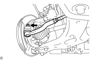
Connect the tie rod end to the steering knuckle with the nut.
- Torque:
- 49 N*m { 500 kgf*cm, 36 ft.*lbf }
Note
Tighten the nut up to an additional 60° if the holes for the cotter pin are not aligned.
-
Install a new cotter pin.
-
-
CONNECT TIE ROD END SUB-ASSEMBLY RH
Tech Tips
Use the same procedure described for the LH side.
-
CONNECT NO. 2 STEERING INTERMEDIATE SHAFT ASSEMBLY
-
Align the matchmarks and install the No. 2 steering intermediate shaft assembly to the intermediate shaft.
-
Install the bolt.
- Torque:
- 35.3 N*m { 360 kgf*cm, 26 ft.*lbf }
-
-
INSTALL COLUMN HOLE COVER SILENCER SHEET
-
INSTALL REAR ENGINE UNDER COVER LH
-
INSTALL REAR ENGINE UNDER COVER RH
-
INSTALL FRONT FLOOR COVER
-
INSTALL NO. 1 ENGINE UNDER COVER
for 2AD Engine: Click here
for 2AR-FE and 3ZR-FE: Click here
for 3ZR-FAE Engine: Click here
for 2WW: Click here
-
INSTALL FRONT WHEELS
- Torque:
- 103 N*m { 1050 kgf*cm, 76 ft.*lbf }
-
POSITION FRONT WHEELS FACING STRAIGHT AHEAD
-
ADJUST FRONT WHEEL ALIGNMENT