STEERING GEAR REASSEMBLY

PROCEDURE
-
INSTALL NO. 2 STEERING RACK BOOT
-
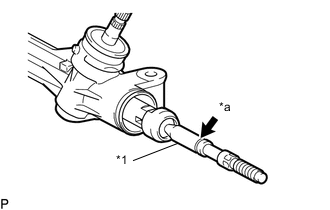
*1 Steering Rack End *a Grease Application Area Apply lithium soap base glycol grease to the inside of the steering rack end.
-
Install the No. 2 steering rack boot to the groove on the rack housing.
Note
-
Be careful not to damage or twist the boot.
-
Make sure that the boot is free of rust and foreign matter.
-
-
-
INSTALL NO. 1 STEERING RACK BOOT
Tech Tips
Use the same procedure as for the No. 2 steering rack boot.
-
TIGHTEN NO. 2 STEERING RACK BOOT CLAMP
-
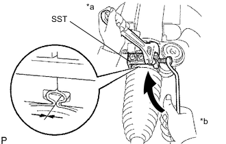
*a Hold *b Turn Using SST, tighten a new No. 2 steering rack boot clamp as shown in the illustration.
- SST
- 09616-00011
Clearance 3.0 mm (0.118 in.) or less Note
Be careful not to damage or twist the boot.
-
-
TIGHTEN NO. 1 STEERING RACK BOOT CLAMP
Tech Tips
Use the same procedure as for the No. 2 steering rack boot clamp.
-
INSTALL STEERING RACK BOOT CLIP
-
Using pliers, install the 2 boot clips.
-
-
INSPECT STEERING GEAR ASSEMBLY
-
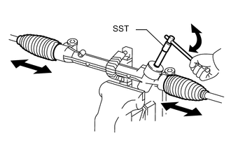
Using SST, rotate the pinion shaft to see if both the left and right steering rack boots expand and contract smoothly.
- SST
- 09616-00011
Tech Tips
If the result is not as specified, use a new steering rack boot clamp and reinstall the steering rack boots.
-
-
INSTALL TIE ROD END SUB-ASSEMBLY LH
-
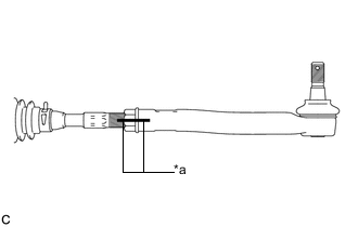
*a Matchmark Install the lock nut and tie rod end sub-assembly LH to the steering gear assembly so that the matchmarks align.
Tech Tips
After adjusting toe-in, tighten the lock nut to the specified torque.
-
-
INSTALL TIE ROD END SUB-ASSEMBLY RH
Tech Tips
Use the same procedure described for the LH side.
-
CHECK TIE ROD END SUB-ASSEMBLY
-
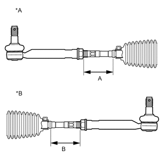
*A for LH Side *B for RH Side Adjust the tie rod end sub-assembly LH and RH so that distance A and distance B are within the specified ranges.
Reference Values Tire size Dimension Standard Range 225/65R17 A 76.4 to 78.4 mm (3.008 to 3.086 in.) B 76.4 to 78.4 mm (3.008 to 3.086 in.) 235/55R18 A 80.1 to 82.1 mm (3.154 to 3.232 in.) B 80.1 to 82.1 mm (3.154 to 3.232 in.) Tech Tips
-
The values listed above are reference values.
-
The toe-in is adjusted in a later step.
-
-