STEERING PAD SWITCH INSPECTION
PROCEDURE
-
INSPECT STEERING PAD SWITCH ASSEMBLY
-
Inspect the pad switch.
-
Measure the resistance according to the value(s) in the table below.
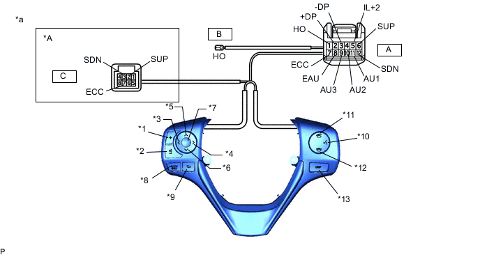
*A w/ Shift Paddle Switch - - *1 Volume+ Switch *2 Volume- Switch *3 Left Switch *4 Right Switch *5 Up Switch *6 Down Switch *7 ENTER Switch *8 MODE Switch *9 Back Switch *10 w/ Voice Switch *11 Off Hook Switch *12 On Hook Switch *13 DISP Switch - - *a Component without harness connected
(Steering Pad Switch Assembly)
- - Standard Resistance Tester Connection Switch Condition Specified Condition A11 (AU1) - A8 (EAU) No switch is pushed 95 to 105 kΩ Volume+ is pushed 950 to 1050 Ω Volume- is pushed 2954 to 3265 Ω Up switch is pushed Below 2.5 Ω Down switch is pushed 312 to 345 Ω A9 (AU3) - A8 (EAU) No switch is pushed 95 to 105 kΩ Left switch is pushed 2954 to 3265 Ω Right switch is pushed 950 to 1050 Ω ENTER Switch is pushed Below 2.5 Ω Back Switch is pushed 312 to 345 Ω A10 (AU2) - A8 (EAU) No switch is pushed 95 to 105 kΩ MODE switch is pushed Below 2.5 Ω On Hook switch is pushed 312 to 345 Ω Off Hook switch is pushed 950 to 1050 Ω Voice switch is pushed 2954 to 3265 Ω A2 (+DP) - A3 (-DP) DISP switch is pushed Below 2.5 Ω A1 (HO) - B (HO) Always Below 2.5 Ω A6 (SUP) - C2 (SUP) Always Below 2.5 Ω A12 (SDN) - C3 (SDN) Always Below 2.5 Ω A7 (ECC) - C7 (ECC) Always Below 2.5 Ω If the result is not as specified, replace the steering pad switch assembly.
-
Connect the battery positive (+) lead to terminal A5 (IL+2) and the negative (-) lead to terminal A8 (EAU) of the steering pad switch assembly connector.
-
Check that the switch illumination comes on.
OK Steering pad switch illumination comes on. If the result is not as specified, replace the steering pad switch assembly.
-
-
Inspect the pad switch.
-
Measure the resistance according to the value(s) in the table below.
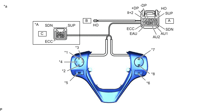
*A w/ Shift Paddle Switch - - *1 Volume+ Switch *2 Volume- Switch *3 Seek+ Switch *4 Seek- Switch *5 MODE Switch *6 DISP Switch *7 w/ Off Hook Switch *8 w/ On Hook Switch *a Component without harness connected
(Steering Pad Switch Assembly)
- - Standard Resistance Tester Connection Switch Condition Specified Condition A11 (AU1) - A8 (EAU) No switch is pushed 95 to 105 kΩ Volume+ is pushed 950 to 1050 Ω Volume- is pushed 2954 to 3265 Ω Seek+ switch is pushed Below 2.5 Ω Seek- switch is pushed 312 to 345 Ω A10 (AU2) - A8 (EAU) No switch is pushed 95 to 105 kΩ MODE switch is pushed Below 2.5 Ω On Hook switch is pushed 312 to 345 Ω Off Hook switch is pushed 950 to 1050 Ω A2 (+DP) - A3 (-DP) DISP switch is pushed Below 2.5 Ω A5 (HO) - B (HO) Always Below 2.5 Ω A6 (SUP) - C2 (SUP) Always Below 2.5 Ω A12 (SDN) - C3 (SDN) Always Below 2.5 Ω A7 (ECC) - C7 (ECC) Always Below 2.5 Ω If the result is not as specified, replace the steering pad switch assembly.
-
Connect the battery positive (+) lead to terminal A1 (IL+2) and the negative (-) lead to terminal A8 (EAU) of the steering pad switch assembly connector.
-
Check that the switch illumination comes on.
OK Steering pad switch illumination comes on. If the result is not as specified, replace the steering pad switch assembly.
-
-