STEERING COLUMN ASSEMBLY INSTALLATION
CAUTION / NOTICE / HINT
Tech Tips
-
Use the same procedure for RHD and LHD vehicles.
-
The procedure listed below is for LHD vehicles.
PROCEDURE
-
INSTALL NO. 2 STEERING INTERMEDIATE SHAFT ASSEMBLY
-
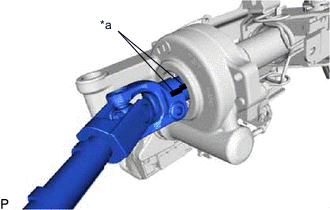
*a Matchmark Align the matchmarks on the No. 2 steering intermediate shaft assembly and steering column assembly.
-
Install the bolt.
- Torque:
- 35.3 N*m { 360 kgf*cm, 26 ft.*lbf }
-
-
INSTALL ELECTRIC POWER STEERING COLUMN SUB-ASSEMBLY
-
Install the steering column assembly with the bolt and 2 nuts.
- Torque:
- for Bolt
- 36 N*m { 367 kgf*cm, 27 ft.*lbf }
- for Nut
- 25 N*m { 255 kgf*cm, 18 ft.*lbf }
Note
-
Do not damage the 2 bushings.
-
Do not line-up the bolt hole by prying on the collar or bushings. Only install the bolt straight, without applying any force to the bushings.
-
Connect the connectors and attach the wire harness clamps to the steering column assembly.
-
Connect the wire harness with the bolt.
- Torque:
- 8.35 N*m { 85 kgf*cm, 74 in.*lbf }
-
-
PLACE FRONT WHEELS FACING STRAIGHT AHEAD
-
CONNECT NO. 2 STEERING INTERMEDIATE SHAFT ASSEMBLY
-
Align the matchmarks on the No. 2 steering intermediate shaft assembly and steering intermediate shaft assembly.
-
Install the bolt.
- Torque:
- 35.3 N*m { 360 kgf*cm, 26 ft.*lbf }
-
-
INSTALL UPPER INSTRUMENT PANEL
-
INSTALL COLUMN HOLE COVER SILENCER SHEET
-
Install the column hole cover silencer sheet with the 2 clips.
-
Install the floor carpet.
-
-
INSTALL NO. 1 LOWER INSTRUMENT PANEL AIRBAG ASSEMBLY (w/ Driver Side Knee Airbag)
-
INSTALL LOWER INSTRUMENT PANEL FINISH PANEL (w/o Driver Side Knee Airbag)
-
INSTALL NO. 1 INSTRUMENT PANEL UNDER COVER SUB-ASSEMBLY
-
INSTALL COMBINATION SWITCH ASSEMBLY WITH SPIRAL CABLE SUB-ASSEMBLY
-
Attach the 3 claws to install the combination switch assembly with spiral cable sub-assembly to the steering column assembly.
-
Connect the connectors to the combination switch assembly with spiral cable sub-assembly.
-
-
INSTALL STEERING COLUMN COVER
-
Attach the 4 clips, 3 claws and 2 pins to install the upper steering column cover.
-
Attach the 2 claws to install the lower steering column cover.
-
Attach the 3 claws.
-
-
INSTALL STEERING WHEEL ASSEMBLY
-
INSPECT STEERING WHEEL CENTER POINT
-
CONNECT CABLE TO NEGATIVE BATTERY TERMINAL
Note
When disconnecting the cable, some systems need to be initialized after the cable is reconnected Click here.
-
INITIALIZE ROTATION ANGLE SENSOR AND CALIBRATE TORQUE SENSOR ZERO POINT
-
CHECK SRS WARNING LIGHT
w/ Occupant Classification System: Click here
w/o Occupant Classification System: Click here