BRAKE BOOSTER(for LHD) INSTALLATION
PROCEDURE
-
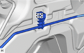
INSTALL VACUUM SENSOR GROMMET (w/ Stop And Start System)
-
INSTALL VACUUM SENSOR ASSEMBLY (w/ Stop And Start System)
-
INSTALL CHECK VALVE GROMMET
-
Install a new check valve grommet to the brake booster assembly.
-
-
INSTALL BRAKE VACUUM CHECK VALVE ASSEMBLY
-
Install the brake vacuum check valve assembly to the check valve grommet.
-
-
INSTALL BRAKE BOOSTER GASKET
-
Install a new brake booster gasket to the brake booster assembly.
-
-
INSTALL BRAKE MASTER CYLINDER PUSH ROD CLEVIS
-
Install the push rod clevis to the brake booster assembly.
-
-
INSTALL BRAKE BOOSTER ASSEMBLY
-
Install the brake booster assembly with the 4 nuts.
- Torque:
- 12.7 N*m { 130 kgf*cm, 9 ft.*lbf }
-
-
INSTALL PUSH ROD PIN
-
INSTALL BRAKE PEDAL RETURN SPRING
-
CHECK AND ADJUST BRAKE BOOSTER PUSH ROD
-
CONNECT VACUUM HOSE
-
Connect the vacuum hose to the brake vacuum check valve assembly, and slide the clip to secure it.
-
-
INSTALL BRAKE MASTER CYLINDER SUB-ASSEMBLY
-
INSTALL BRAKE ACTUATOR ASSEMBLY WITH BRACKET
-
CONNECT BRAKE LINE
-
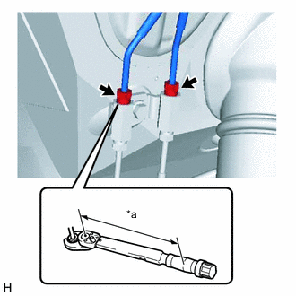
*a Torque Wrench Fulcrum Length Using a union nut wrench, connect the 2 brake tubes to the 2-way.
- Torque:
- Specified tightening torque
- 15.2 N*m { 155 kgf*cm, 11 ft.*lbf }
Tech Tips
-
Calculate the torque wrench reading when changing the fulcrum length of the torque wrench.
-
When using a union nut wrench (fulcrum length of 22 mm (0.866 in.)) + torque wrench (fulcrum length of 162 mm (6.378 in.)) : 13.4 N*m (137kgf*cm, 10 ft.*lbf)
-
Install a new No. 4 brake tube clamp and the brake tube to the body.
-
-
INSTALL COWL BODY MOUNTING REINFORCEMENT LH
-
Install the cowl body mounting reinforcement LH with the 2 nuts.
- Torque:
- 50 N*m { 510 kgf*cm, 37 ft.*lbf }
-
-
INSTALL COWL TOP PANEL OUTER SUB-ASSEMBLY
-
Install the cowl top panel outer sub-assembly with the 13 bolts.
- Torque:
- 5.5 N*m { 56 kgf*cm, 49 in.*lbf }
-
-
INSTALL COWL VENTILATOR HOUSING SUB-ASSEMBLY
-
Engage the 3 clips to install the cowl ventilator housing sub-assembly.
-
-
INSTALL WINDSHIELD WIPER MOTOR AND LINK ASSEMBLY
-
INSTALL AIR CLEANER CASE SUB-ASSEMBLY
-
for 2AR-FE:
-
for 3ZR-FE:
-
for 3ZR-FAE:
-
for 2AD-FHV:
-
for 2AD-FTV:
-
for 2WW:
-
-
INSTALL LOWER NO. 1 INSTRUMENT PANEL AIRBAG ASSEMBLY (w/ Driver Side Knee Airbag)
-
INSTALL LOWER INSTRUMENT PANEL FINISH PANEL (w/o Driver Side Knee Airbag)
-
CONNECT CABLE TO NEGATIVE BATTERY TERMINAL
Note
When disconnecting the cable, some systems need to be initialized after the cable is reconnected Click here.
-
BLEED BRAKE SYSTEM
-
BLEED CLUTCH LINE (for Manual Transaxle)
-
for 2AD-FTV:
-
for 2AR-FE:
-
for 3ZR-FE:
-
for 3ZR-FAE:
-
for 2WW:
-
-
INSPECT AND ADJUST BRAKE PEDAL