VEHICLE STABILITY CONTROL SYSTEM Downhill Assist Control Indicator Light Remains ON
DESCRIPTION
When the downhill assist control switch is turned on, the downhill assist control function is available and the downhill assist control indicator light illuminates.
CAUTION / NOTICE / HINT
Note
When replacing the skid control ECU (brake actuator assembly), perform zero point calibration.
PROCEDURE
-
CHECK IF SKID CONTROL ECU CONNECTOR IS SECURELY CONNECTED
-
Check if the skid control ECU (brake actuator assembly) connector is securely connected.
OK The connector is securely connected. Result Proceed to OK NG
NG 
CONNECT CONNECTOR TO ECU CORRECTLY
OK 
-
-
CHECK CAN COMMUNICATION SYSTEM
-
Check if CAN communication system DTCs are output.
for LHD: Click here
for RHD: Click here
Result Proceed to DTC is not output DTC is output (for LHD) DTC is output (for RHD)
DTC is output (for LHD)
CHECK CAN COMMUNICATION SYSTEM Click here
DTC is output (for RHD)
CHECK CAN COMMUNICATION SYSTEM Click here
DTC is not output
-
-
CHECK HARNESS AND CONNECTOR (HDCS TERMINAL)
-
Turn the ignition switch off.
-
Disconnect the A64 skid control ECU (brake actuator assembly) connector.
-
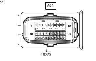
Measure the resistance according to the value(s) in the table below.
Standard Resistance Tester Connection Switch Condition Specified Condition A64-29 (HDCS) - Body ground Downhill assist control switch is pushed Below 1 Ω A64-29 (HDCS) - Body ground Downhill assist control switch is not pushed 10 kΩ or higher Result Proceed to OK NG
NG 
INSPECT DOWNHILL ASSIST CONTROL SWITCH Click here
OK
-
-
READ VALUE USING GTS (DOWNHILL ASSIST CONTROL LIGHT)
-
Reconnect the A64 skid control ECU (brake actuator assembly) connector.
-
Connect the GTS to the DLC3.
-
Turn the ignition switch to ON.
-
Turn the GTS on.
-
Enter the following menus: Chassis / ABS/VSC/TRC / Data List.
-
According to the display on the GTS, read the Data List.
Chassis > ABS/VSC/TRC > Data ListTester Display Measurement Item Range Normal Condition Diagnostic Note Downhill Assist Control Light Downhill assist control indicator light ON or OFF ON: Indicator light on
OFF: Indicator light off
-
Chassis > ABS/VSC/TRC > Data ListTester Display Downhill Assist Control Light -
Check the GTS display condition of the Downhill assist control indicator light.
Result Proceed to Display of the Data List remains OFF Display of the Data List remains ON
Display of the Data List remains OFF
INSPECT METER / GAUGE SYSTEM Click here
Display of the Data List remains ON
REPLACE BRAKE ACTUATOR ASSEMBLY Click here
-
-
INSPECT DOWNHILL ASSIST CONTROL SWITCH
-
Turn the ignition switch off.
-
Remove the downhill assist control switch.
-
Inspect the downhill assist control switch.
Result Result OK NG
NG
REPLACE DOWNHILL ASSIST CONTROL SWITCH Click here
OK
-
-
CHECK HARNESS AND CONNECTOR (BRAKE ACTUATOR ASSEMBLY - DOWNHILL ASSIST CONTROL SWITCH)
-
Measure the resistance according to the value(s) in the table below.
Standard Resistance Tester Connection Condition Specified Condition A64-29 (HDCS) - G29-4 Always Below 1 Ω A64-29 (HDCS) or G29-4 - Body ground Always 10 kΩ or higher G29-1 - Body ground Always Below 1 Ω Result Result OK NG
OK
USE SIMULATION METHOD TO CHECK Click here
NG
REPAIR OR REPLACE HARNESS OR CONNECTOR
-