VEHICLE STABILITY CONTROL SYSTEM TRC OFF Indicator Light does not Come ON
CAUTION / NOTICE / HINT
PROCEDURE
-
CHECK CAN COMMUNICATION SYSTEM
-
Check if CAN communication system DTCs are output.
for LHD: Click here
for RHD: Click here
Result Proceed to DTC is not output DTC is output (for LHD) DTC is output (for RHD)
DTC is output (for LHD) 
CHECK CAN COMMUNICATION SYSTEM Click here
DTC is output (for RHD)
CHECK CAN COMMUNICATION SYSTEM Click here
DTC is not output 
-
-
CHECK HARNESS AND CONNECTOR (CSW TERMINAL)
-
Turn the ignition switch off.
-
Disconnect the A64 skid control ECU (brake actuator assembly) connector.
-
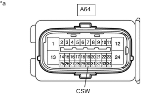
*a Front view of wire harness connector
(to Skid Control ECU [Brake Actuator Assembly])
Measure the resistance according to the value(s) in the table below.
Standard Resistance Tester Connection Switch Condition Specified Condition A64-30 (CSW) - Body ground VSC OFF switch held on Below 1 Ω A64-30 (CSW) - Body ground VSC OFF switch off (Not pressed) 10 kΩ or higher Result Proceed to OK NG
NG 
INSPECT TRACTION CONTROL SWITCH Click here
OK
-
-
READ VALUE USING GTS (TRC/VSC OFF MODE)
-
Reconnect the A64 skid control ECU (brake actuator assembly) connector.
-
Connect the GTS to the DLC3.
-
Turn the ignition switch to ON.
-
Turn the GTS on.
-
Enter the following menus: Chassis / ABS/VSC/TRC / Data List.
-
According to the display on the GTS, read the Data List.
Chassis > ABS/VSC/TRC > Data ListTester Display Measurement Item Range Normal Condition Diagnostic Note TRC/VSC Off Mode TRC/TRAC/VSC off mode Normal, TRC OFF, Unknown or VSC OFF Normal: Normal mode
TRC OFF: TRC/TRAC off mode
VSC OFF: VSC off mode
Unknown: Unspecified
Chassis > ABS/VSC/TRC > Data ListTester Display TRC/VSC Off Mode -
Check that the mode display changes according to the VSC OFF switch (traction control switch) operation.
OK Display changes according to the switch operation. Result Proceed to OK NG
NG
REPLACE BRAKE ACTUATOR ASSEMBLY Click here
OK
-
-
INSPECT COMBINATION METER ASSEMBLY
-
for Segment Display Type:
-
Perform Active Test of the combination meter assembly using the GTS.
Body Electrical > Combination Meter > Active TestTester Display VSC TRC Indicator -
Check the combination meter assembly.
OK The TRC/TRAC OFF indicator light turns on or off in accordance with the GTS.
-
-
for Dot Display Type:
-
Perform Active Test of the combination meter assembly using the GTS.
Body Electrical > Combination Meter > Active TestTester Display Meter Display 1 -
Check the combination meter assembly.
OK The multi-information display turns on or off in accordance with the GTS operation
Result Proceed to OK NG -
OK
REPLACE BRAKE ACTUATOR ASSEMBLY Click here
NG
INSPECT METER / GAUGE SYSTEM Click here
-
-
INSPECT TRACTION CONTROL SWITCH
-
Remove the VSC OFF switch (traction control switch).
-
Inspect the VSC OFF switch (traction control switch).
Result Proceed to OK NG
NG
REPLACE TRACTION CONTROL SWITCH Click here
OK
-
-
CHECK HARNESS AND CONNECTOR (BRAKE ACTUATOR ASSEMBLY - TRACTION CONTROL SWITCH)
-
Measure the resistance according to the value(s) in the table below.
Standard Resistance Tester Connection Condition Specified Condition A64-30 (CSW) - G51-6 (+) Always Below 1 Ω G51-3 (E) - Body ground Always Below 1 Ω A64-30 (CSW) or G51-6 (+) - Body ground Always 10 kΩ or higher Result Proceed to OK NG
OK
USE SIMULATION METHOD TO CHECK Click here
NG
REPAIR OR REPLACE HARNESS OR CONNECTOR
-