NAVIGATION SYSTEM(for HDD), Diagnostic DTC:B1579
| DTC Code | DTC Name |
|---|---|
| B1579 | Voice Recognition Microphone Disconnected |
DESCRIPTION
The navigation ECU sub-assembly and map light assembly (telephone microphone assembly) are connected to each other using the microphone connection detection signal lines.
This DTC is stored when a microphone connection detection signal line is disconnected.
| DTC No. | Detection Item | DTC Detection Condition | Trouble Area |
|---|---|---|---|
| B1579 | Voice Recognition Microphone Disconnected | Telephone microphone signal is lost. |
|
WIRING DIAGRAM
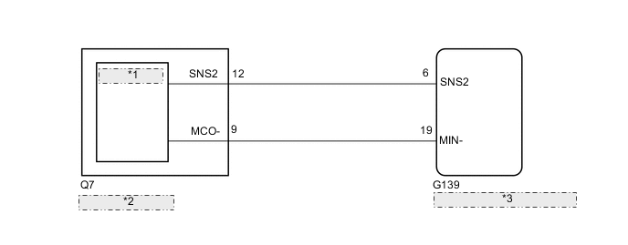
| *1 | Telephone Microphone Assembly |
| *2 | Map Light Assembly |
| *3 | Navigation ECU Sub-assembly |
PROCEDURE
-
CHECK NAVIGATION ECU SUB-ASSEMBLY
-
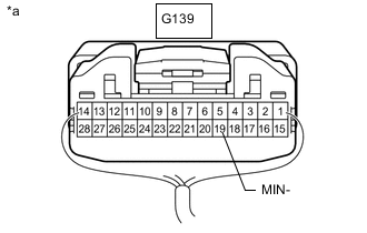
*a Component with harness connected
(Navigation ECU Sub-assembly)
Measure the resistance according to the value(s) in the table below.
Standard Resistance Tester Connection Condition Specified Condition G139-19 (MIN-) - Body ground Always Below 1 Ω Result Proceed to OK NG
NG 
REPLACE NAVIGATION ECU SUB-ASSEMBLY Click here
OK 
-
-
CHECK HARNESS AND CONNECTOR (NAVIGATION ECU SUB-ASSEMBLY - MAP LIGHT ASSEMBLY [TELEPHONE MICROPHONE ASSEMBLY])
-
Disconnect the G139 navigation ECU sub-assembly connector.
-
Disconnect the Q7 map light assembly (telephone microphone assembly) connector.
-
Measure the resistance according to the value(s) in the table below.
Standard Resistance Tester Connection Condition Specified Condition G139-6 (SNS2) - Q7-12 (SNS2) Always Below 1 Ω G139-19 (MIN-) - Q7-9 (MCO-) Always Below 1 Ω G139-6 (SNS2) - Body ground Always 10 kΩ or higher G139-19 (MIN-) - Body ground Always 10 kΩ or higher Result Proceed to OK NG
NG
REPAIR OR REPLACE HARNESS OR CONNECTOR
OK
-
-
INSPECT MAP LIGHT ASSEMBLY (TELEPHONE MICROPHONE ASSEMBLY)
-
Remove the map light assembly (telephone microphone assembly).
-
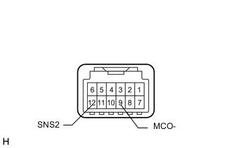
Measure the resistance according to the value(s) in the table below.
Standard Resistance Tester Connection Condition Specified Condition 12 (SNS2) - 9 (MCO-) Always Below 1 Ω Result Proceed to OK NG
OK
REPLACE NAVIGATION ECU SUB-ASSEMBLY Click here
NG
-
-
CHECK TELEPHONE MICROPHONE ASSEMBLY
-
Replace the telephone microphone assembly with a new or normally functioning one.
-
Clear the DTCs.
Body Electrical > Navigation System > Clear DTCs -
Recheck for DTCs and check if the same DTC is output again.
Body Electrical > Navigation System > Trouble CodesResult Proceed to No DTCs are output DTCs are output
No DTCs are output
END (TELEPHONE MICROPHONE ASSEMBLY IS DEFECTIVE)
DTCs are output
-
-
CHECK MAP LIGHT ASSEMBLY
-
Replace the map light assembly with a new or normally functioning one.
-
Clear the DTCs.
Body Electrical > Navigation System > Clear DTCs -
Recheck for DTCs and check if the same DTC is output again.
Body Electrical > Navigation System > Trouble CodesResult Proceed to No DTCs are output DTCs are output
No DTCs are output
END (MAP LIGHT ASSEMBLY IS DEFECTIVE)
DTCs are output
REPLACE NAVIGATION ECU SUB-ASSEMBLY Click here
-