REAR SUSPENSION MEMBER REMOVAL

PROCEDURE
-
REMOVE REAR WHEEL
-
REMOVE REAR HEIGHT CONTROL SENSOR SUB-ASSEMBLY LH (w/ Automatic Headlight Beam Level Control System)
-
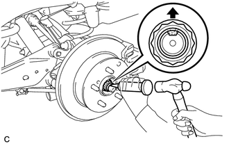
REMOVE REAR AXLE SHAFT NUT LH (for 4WD/AWD)
-
Using SST and a hammer, unstake the staked part of the rear axle shaft nut.
- SST
- 09930-00010 ( 09931-00010, 09931-00020 )
Note
Loosen the staked part of the rear axle shaft nut completely, otherwise the screw of the drive shaft may be damaged.
-
While applying the brakes, remove the rear axle shaft nut.
-
-
REMOVE REAR AXLE SHAFT NUT RH (for 4WD/AWD)
Tech Tips
Use the same procedure described for the LH side.
-
DISCONNECT SKID CONTROL SENSOR WIRE LH (for 2WD)
-
DISCONNECT SKID CONTROL SENSOR WIRE RH (for 2WD)
Tech Tips
Use the same procedure described for the LH side.
-
DISCONNECT REAR SPEED SENSOR LH (for 4WD/AWD)
-
DISCONNECT REAR SPEED SENSOR RH (for 4WD/AWD)
Tech Tips
Use the same procedure described for the LH side.
-
DISCONNECT NO. 3 PARKING BRAKE CABLE ASSEMBLY
-
DISCONNECT NO. 2 PARKING BRAKE CABLE ASSEMBLY
Tech Tips
Use the same procedure described for the No. 3 parking brake cable assembly.
-
DISCONNECT REAR DISC BRAKE CALIPER ASSEMBLY LH
-
DISCONNECT REAR DISC BRAKE CALIPER ASSEMBLY RH
Tech Tips
Use the same procedure described for the LH side.
-
REMOVE REAR DISC
-
REMOVE PARKING BRAKE ASSEMBLY
-
REMOVE REAR AXLE HUB AND BEARING ASSEMBLY LH (for 2WD)
-
REMOVE REAR AXLE HUB AND BEARING ASSEMBLY RH (for 2WD)
Tech Tips
Use the same procedure described for the LH side.
-
REMOVE REAR AXLE HUB AND BEARING ASSEMBLY LH (for 4WD/AWD)
-
REMOVE REAR AXLE HUB AND BEARING ASSEMBLY RH (for 4WD/AWD)
Tech Tips
Use the same procedure described for the LH side.
-
REMOVE REAR SUSPENSION MEMBER BRACE LH
-
REMOVE REAR SUSPENSION MEMBER BRACE RH
Tech Tips
Use the same procedure described for the LH side.
-
REMOVE REAR STABILIZER LINK ASSEMBLY LH
-
REMOVE REAR STABILIZER LINK ASSEMBLY RH
Tech Tips
Use the same procedure described for the LH side.
-
REMOVE REAR STABILIZER BAR
-
REMOVE REAR NO. 1 SUSPENSION ARM ASSEMBLY LH
-
REMOVE REAR NO. 1 SUSPENSION ARM ASSEMBLY RH
Tech Tips
Use the same procedure described for the LH side.
-
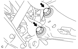
DISCONNECT REAR TRAILING ARM ASSEMBLY LH
-
Remove the 2 bolts and disconnect the rear trailing arm.
-
-
DISCONNECT REAR TRAILING ARM ASSEMBLY RH
Tech Tips
Use the same procedure described for the LH side.
-
LOOSEN REAR NO. 2 SUSPENSION ARM ASSEMBLY LH
-
LOOSEN REAR NO. 2 SUSPENSION ARM ASSEMBLY RH
Tech Tips
Use the same procedure described for the LH side.
-
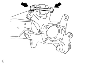
REMOVE REAR AXLE CARRIER SUB-ASSEMBLY LH
-
Remove the bolt and nut, disconnect the rear upper control arm and remove the rear axle carrier.
Note
Since a stopper nut is used, loosen the bolt.
-
-
REMOVE REAR AXLE CARRIER SUB-ASSEMBLY RH
Tech Tips
Use the same procedure described for the LH side.
-
REMOVE REAR SHOCK ABSORBER ASSEMBLY LH
-
REMOVE REAR SHOCK ABSORBER ASSEMBLY RH
Tech Tips
Use the same procedure described for the LH side.
-
REMOVE REAR COIL SPRING LH
-
REMOVE REAR COIL SPRING RH
Tech Tips
Use the same procedure described for the LH side.
-
REMOVE REAR UPPER COIL SPRING INSULATOR LH
-
REMOVE REAR UPPER COIL SPRING INSULATOR RH
Tech Tips
Use the same procedure described for the LH side.
-
REMOVE REAR LOWER COIL SPRING INSULATOR LH
-
REMOVE REAR LOWER COIL SPRING INSULATOR RH
Tech Tips
Use the same procedure described for the LH side.
-
REMOVE REAR NO. 2 SUSPENSION ARM ASSEMBLY LH
-
REMOVE REAR NO. 2 SUSPENSION ARM ASSEMBLY RH
Tech Tips
Use the same procedure described for the LH side.
-
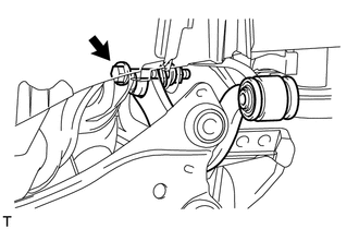
REMOVE REAR UPPER CONTROL ARM ASSEMBLY LH
-
Remove the bolt, nut and upper control arm from the rear suspension member.
-
-
REMOVE REAR UPPER CONTROL ARM ASSEMBLY RH
Tech Tips
Use the same procedure described for the LH side.
-
REMOVE PROPELLER WITH CENTER BEARING SHAFT ASSEMBLY (for 4WD/AWD)
-
REMOVE REAR DIFFERENTIAL CARRIER ASSEMBLY (for 4WD/AWD)
-
REMOVE REAR SUSPENSION MEMBER SUB-ASSEMBLY
-
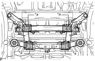
*a Attachment Placement Positions Place wooden blocks or plate lift attachments in the positions shown in the illustration and set an engine lifter underneath the suspension member.
Note
-
Place the wooden blocks or plate lift attachments so that the rear suspension member sub-assembly is level.
-
As the rear suspension member sub-assembly is very heavy, be sure to support it securely.
-
-
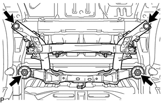
Remove the 2 bolts, 2 nuts, 2 rear upper body mounting cushions and rear suspension member sub-assembly.
-
-
REMOVE REAR NO. 1 DIFFERENTIAL MOUNT CUSHION (for 4WD/AWD)