FRONT LOWER SUSPENSION ARM REMOVAL

CAUTION / NOTICE / HINT
Tech Tips
-
Use the same procedure for the RH and LH sides.
-
The procedure listed below is for the LH side.
PROCEDURE
-
FRONT WHEELS FACING STRAIGHT AHEAD
-
REMOVE FRONT WHEELS
-
REMOVE NO. 1 ENGINE UNDER COVER
for AD Series Engine: Click here
for 2AR and 3ZR-FE Engine: Click here
for 3ZR-FAE Engine: Click here
-
REMOVE FRONT FLOOR COVER
-
REMOVE REAR ENGINE UNDER COVER RH
-
Remove the 3 clips and under cover.
-
-
REMOVE REAR ENGINE UNDER COVER LH
-
Remove the 3 clips and under cover.
-
-
SECURE STEERING WHEEL
-
REMOVE COLUMN HOLE COVER SILENCER SHEET
-
DISCONNECT NO. 2 STEERING INTERMEDIATE SHAFT ASSEMBLY
-
REMOVE NO. 1 STEERING COLUMN HOLE COVER SUB-ASSEMBLY
-
DISCONNECT FRONT STABILIZER LINK ASSEMBLY LH
-
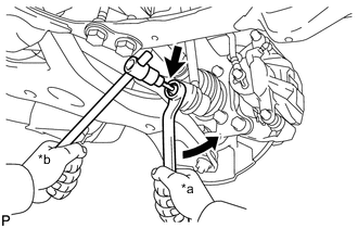
*a Turn *b Hold Remove the nut and disconnect the front stabilizer link assembly LH from the front stabilizer bar.
Tech Tips
If the ball joint turns together with the nut, use a 6 mm hexagon wrench to hold the stud bolt.
-
-
DISCONNECT FRONT STABILIZER LINK ASSEMBLY RH
Tech Tips
Use the same procedure described for the LH side.
-
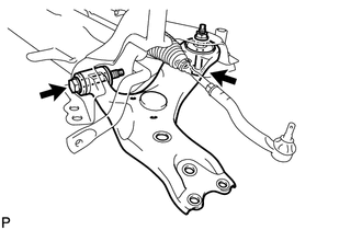
DISCONNECT TIE ROD END SUB-ASSEMBLY LH
-
DISCONNECT TIE ROD END SUB-ASSEMBLY RH
Tech Tips
Use the same procedure described for the LH side.
-
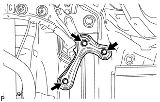
DISCONNECT FRONT LOWER NO. 1 SUSPENSION ARM SUB-ASSEMBLY LH
-
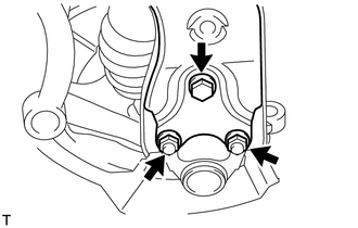
Remove the bolt and 2 nuts.
-
Disconnect the front lower No. 1 suspension arm from the lower ball joint.
-
-
DISCONNECT FRONT LOWER NO. 1 SUSPENSION ARM SUB-ASSEMBLY RH
Tech Tips
Use the same procedure described for the LH side.
-
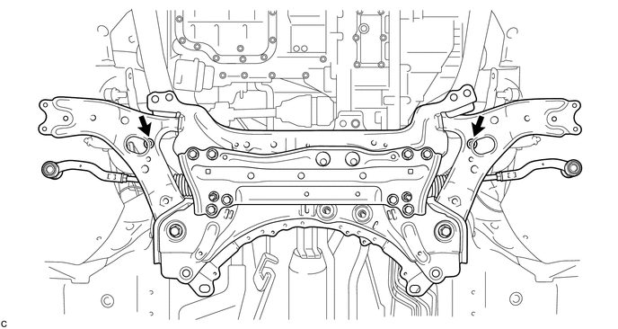
REMOVE FRONT SUSPENSION MEMBER REINFORCEMENT LH
-
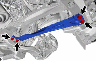
Remove the 4 bolts and front suspension member reinforcement LH.
-
-
REMOVE FRONT SUSPENSION MEMBER REINFORCEMENT RH
-
Remove the 4 bolts and front suspension member reinforcement RH.
-
-
REMOVE ENGINE FRONT MOUNTING BRACKET REINFORCEMENT LOWER (for 1AD and 3ZR 2WD)
-
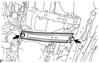
Remove the 2 bolts and engine front mounting bracket reinforcement lower.
-
-
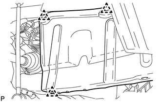
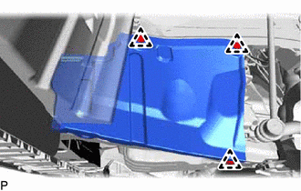
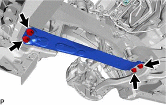
REMOVE FRONT SUSPENSION MEMBER REAR BRACE LH
-
Remove the 3 bolts and front suspension member rear brace LH.
-
-
REMOVE FRONT SUSPENSION MEMBER REAR BRACE RH
Tech Tips
Use the same procedure described for the LH side.
-
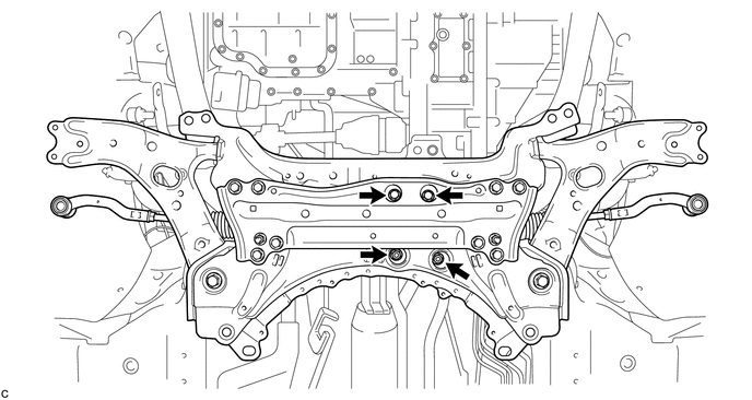
REMOVE FRONT SUSPENSION CROSSMEMBER SUB-ASSEMBLY
-
Remove the 2 bolts and 2 nuts, and disconnect the front suspension crossmember sub-assembly from the rear engine mounting insulator.
-
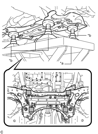
*a Engine Lifter *b Attachment 
Attachment placement location Support the front suspension crossmember sub-assembly with an engine lifter using 4 attachments or equivalent tools as shown in the illustration.
Note
-
Make sure to secure the front suspension crossmember sub-assembly to prevent it from dropping.
-
Use the attachments to keep the front suspension crossmember sub-assembly level.
-
The front suspension crossmember sub-assembly is a heavy component. Make sure that it is supported securely.
-
-
Remove the 2 bolts and front suspension crossmember sub-assembly.
-
Slowly lower the front suspension crossmember sub-assembly.
Note
When lowering the front suspension crossmember sub-assembly, be careful not to damage the vehicle body or other components installed on the vehicle.
-
-
REMOVE FRONT LOWER NO. 1 SUSPENSION ARM SUB-ASSEMBLY LH
-
Remove the 2 bolts, nut and front lower No. 1 suspension arm sub-assembly LH from the front suspension crossmember sub-assembly.
Note
Because the nut has its own stopper, do not turn the nut. Loosen the bolt with the nut secured.
-