FRONT SHOCK ABSORBER INSTALLATION

CAUTION / NOTICE / HINT
Tech Tips
-
Use the same procedure for the RH and LH sides.
-
The procedure listed below is for the LH side.
PROCEDURE
-
INSTALL FRONT SHOCK ABSORBER ASSEMBLY LH
-
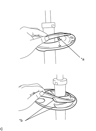
*a Positioning Pin *b Depression Install the front coil spring lower insulator to the front shock absorber assembly.
Note
When installing the insulator, fit the insulator into the depression of the spring seat and insert the positioning pin into the hole.
-
Install the front spring bumper to the front shock absorber assembly.
Note
Position the end of the front spring bumper with the smaller diameter downward.
-
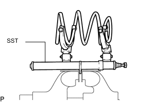
Secure SST in a vise.
- SST
- 09727-30021 ( 09727-00010, 09727-00021, 09727-00031 )
-
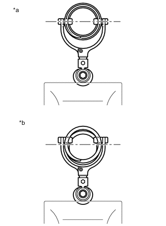
*a Correct *b Incorrect Attach the arm of SST to the diameter of the coil spring.
CAUTION:
-
Make sure that the coil spring is installed so that the distance between the upper and lower hooks of SST is at the maximum.
-
Make sure that the claws of the hooks are securely attached.
-
-
Using SST, compress the coil spring.
CAUTION:
-
If the coil spring bends during the compression, immediately stop the compression and reinstall SST.
-
Do not compress the spring until the coil springs contact each other.
-
Do not use an impact wrench.
-
-
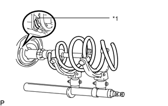
*1 Spring Lower Seat Install the front coil spring so that the end comes to the stepped portion of the spring lower seat.
-
Install the front spring seat sub-assembly with insulator LH.
-
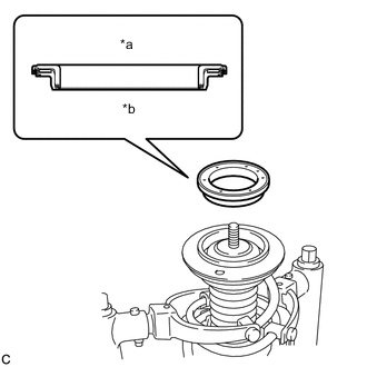
*a Upper Side *b Lower Side Install the strut mounting bearing.
Note
Do not install the bearing upside down.
-
Install the front suspension support sub-assembly to the front shock absorber assembly.
Note
When installing the front suspension support sub-assembly, align the cutout on the front suspension support sub-assembly with the end of the shock absorber piston rod.
-
Install the collar to the front shock absorber assembly.
-
Temporarily install a new front support to front shock absorber nut.
-
Remove SST from the front coil spring.
Note
Do not use an impact wrench. It will damage SST.
-
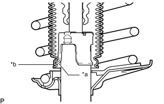
*a Claws of the Front Shock Absorber Assembly LH *b End of the Shock Absorber Dust Cover of the Front Spring Seat Sub-assembly with Insulator LH Connect the end of the shock absorber dust cover of the front spring seat sub-assembly with insulator LH with the claws of the front shock absorber assembly LH.
Note
-
Make sure that the end of the shock absorber dust cover is securely attached to the claws of the front shock absorber assembly LH.
-
Make sure there is no excessive damage to the bellows of the shock absorber dust cover.
-
Do not allow oil, grease, etc., to contact the shock absorber dust cover.
-
If oil or grease has adhered, wipe clean with a cloth. Do not use an alcoholic cleaner.
-
-
-
INSTALL FRONT SUSPENSION SUPPORT PLATE LH
-
Install the front suspension support plate to the front shock absorber with coil spring.
-
-
INSTALL FRONT SHOCK ABSORBER WITH COIL SPRING
-
Install the front shock absorber with coil spring (upper side) and front fender apron rear extension LH with the 3 nuts.
- Torque:
- 50 N*m { 510 kgf*cm, 37 ft.*lbf }
-
Connect the front shock absorber with coil spring (lower side) to the steering knuckle with the 2 bolts and 2 nuts.
- Torque:
- 240 N*m { 2447 kgf*cm, 177 ft.*lbf }
Tech Tips
The bolts can be installed in either direction, however, make sure that they are both installed in the same direction.
-
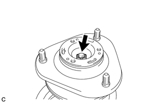
Tighten the front support to front shock absorber nut.
- Torque:
- 47 N*m { 479 kgf*cm, 35 ft.*lbf }
-
-
CONNECT FRONT FLEXIBLE HOSE
-
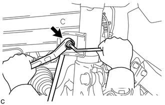
Connect the front flexible hose to the steering knuckle with the bolt.
- Torque:
- 18.5 N*m { 189 kgf*cm, 14 ft.*lbf }
-
-
CONNECT FRONT SPEED SENSOR LH
-
Connect the front flexible hose and front speed sensor with the bolt.
- Torque:
- 18.5 N*m { 189 kgf*cm, 14 ft.*lbf }
Note
Do not twist the front speed sensor when installing it.
Tech Tips
Install the front flexible hose and wire harness bracket of the front speed sensor in that order.
-
-
CONNECT FRONT STABILIZER LINK ASSEMBLY LH
-
Connect the front stabilizer link assembly to the front shock absorber with coil spring with the nut.
- Torque:
- 74 N*m { 755 kgf*cm, 55 ft.*lbf }
Tech Tips
If the ball joint turns together with the nut, use a 6 mm hexagon wrench to hold the stud bolt.
-
-
INSTALL FRONT SUSPENSION SUPPORT DUST COVER LH
-
Install the front suspension support dust cover LH.
-
-
INSTALL FRONT WHEEL
- Torque:
- 103 N*m { 1050 kgf*cm, 76 ft.*lbf }
-
INSPECT AND ADJUST FRONT WHEEL ALIGNMENT