REAR AXLE CARRIER INSTALLATION

PROCEDURE
-
INSTALL REAR AXLE CARRIER SUB-ASSEMBLY LH
-
Temporarily install the rear axle carrier to the rear upper control arm with the bolt and nut.
-
-
TEMPORARILY INSTALL REAR NO. 2 SUSPENSION ARM ASSEMBLY LH
-
Install the rear lower coil spring insulator to the rear No. 2 suspension arm.
-
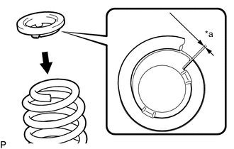
*a 10 mm or less Install the rear upper coil spring insulator to the rear coil spring.
Note
Install the rear upper coil insulator so that the distance between the stopper and upper end of the rear coil spring is 10 mm (0.394 in.) or less.
-
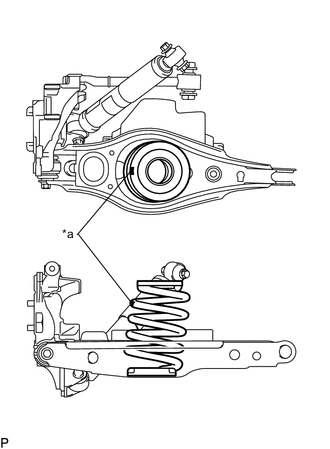
*a Identification Mark Install the rear coil spring to the rear No. 2 suspension arm.
Note
Make sure that the identification mark is positioned towards the outer sides of the vehicle.
-
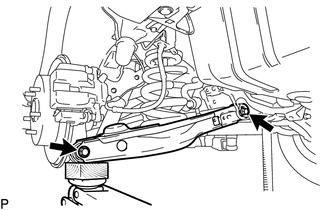
Using a jack and wooden block, raise the vehicle gradually to install the rear No. 2 suspension arm to the rear axle carrier. Then temporarily install the bolt.
Note
-
When jacking up the rear No. 2 suspension arm assembly, be sure to jack it up slowly.
-
Do not jack up the rear No. 2 suspension arm assembly too high as the vehicle may fall.
-
Make sure to perform this operation with the vehicle kept as low as possible.
-
-
-
INSTALL REAR TRAILING ARM ASSEMBLY
-
Install the rear trailing arm to the axle carrier with the 2 bolts.
- Torque:
- 200 N*m { 2039 kgf*cm, 148 ft.*lbf }
-
-
INSTALL REAR NO. 1 SUSPENSION ARM ASSEMBLY LH
-
Install the rear No. 1 suspension arm to the rear axle carrier with a new nut.
- Torque:
- 100 N*m { 1020 kgf*cm, 74 ft.*lbf }
-
-
INSTALL REAR SHOCK ABSORBER BRACKET LH
-
Install the rear shock absorber bracket to the rear axle carrier with the 2 bolts.
- Torque:
- 80 N*m { 816 kgf*cm, 59 ft.*lbf }
-
-
INSTALL REAR HEIGHT CONTROL SENSOR SUB-ASSEMBLY LH (w/ Automatic Headlight Beam Level Control System)
-
STABILIZE SUSPENSION
-
TIGHTEN REAR UPPER CONTROL ARM ASSEMBLY LH
-
Tighten the bolt.
- Torque:
- 90 N*m { 918 kgf*cm, 66 ft.*lbf }
Note
Since a stopper nut is used, tighten the bolt.
-
-
TIGHTEN REAR NO. 2 SUSPENSION ARM ASSEMBLY LH
-
Tighten the bolts of the suspension arm.
- Torque:
- 90 N*m { 918 kgf*cm, 66 ft.*lbf }
-
-
CONNECT PARKING BRAKE ASSEMBLY
-
Connect the parking brake assembly to the rear axle carrier with the nut.
- Torque:
- 140 N*m { 1428 kgf*cm, 103 ft.*lbf }
-
-
CONNECT NO. 3 PARKING BRAKE CABLE ASSEMBLY
-
Connect the No. 3 parking brake cable to the rear trailing arm with the bolt.
- Torque:
- 6.0 N*m { 61 kgf*cm, 53 in.*lbf }
-
-
INSTALL REAR STABILIZER LINK ASSEMBLY LH
-
INSTALL REAR AXLE HUB AND BEARING ASSEMBLY LH (for 2WD)
-
INSTALL REAR AXLE HUB AND BEARING ASSEMBLY LH (for 4WD/AWD)
-
INSTALL REAR AXLE SHAFT NUT LH (for 4WD/AWD)
-
INSPECT REAR AXLE HUB BEARING LOOSENESS
-
INSPECT REAR AXLE HUB RUNOUT
-
INSTALL REAR DISC
-
CONNECT REAR DISC BRAKE CALIPER ASSEMBLY LH
-
CONNECT SKID CONTROL SENSOR WIRE LH (for 2WD)
-
CONNECT REAR SPEED SENSOR LH (for 4WD/AWD)
-
STAKE REAR AXLE SHAFT NUT LH (for 4WD/AWD)
-
INSTALL REAR WHEEL
- Torque:
- 103 N*m { 1050 kgf*cm, 76 ft.*lbf }
-
INSPECT AND ADJUST PARKING BRAKE
-
INSPECT AND ADJUST REAR WHEEL ALIGNMENT
-
CHECK FOR SPEED SENSOR SIGNAL
w/o VSC: Click here
w/ VSC: Click here