FRONT DRIVE SHAFT ASSEMBLY(for 2WD) REASSEMBLY

CAUTION / NOTICE / HINT
Note
-
When using a vise, place aluminum plates between the part and vise.
-
When using a vise, do not overtighten it.
PROCEDURE
-
INSTALL FRONT DRIVE SHAFT BEARING (for RH Side)
-
w/o Drive Shaft Bearing Case:
-
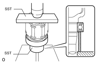
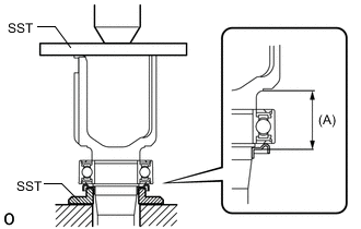
Using SST and a press, install a new front drive shaft bearing to the front drive inboard joint assembly RH.
- SST
- 09527-10011
- 09710-30012 ( 09710-04081 )
Note
-
Make sure the front drive shaft bearing contacts the edge of the front drive inboard joint assembly RH, but do not press it in more than necessary.
-
Do not apply weight to the dust cover and outer race of the front drive shaft bearing.
-
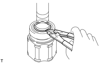
Using a snap ring expander, install a new snap ring.
Note
The Snap ring should be installed completely.
-
-
-
INSTALL DRIVE SHAFT BEARING CASE SUB-ASSEMBLY (for RH Side)
-
w/ Drive Shaft Bearing Case:
-
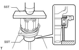
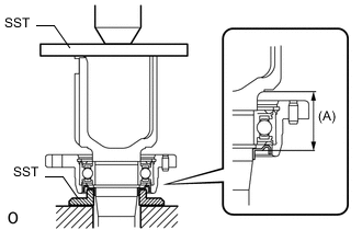
Using SST and a press, install a new drive shaft bearing case sub-assembly to the front drive inboard joint assembly RH.
- SST
- 09527-10011
- 09710-30012 ( 09710-04081 )
Note
-
Make sure the front drive shaft bearing contacts the edge of the front drive inboard joint assembly RH, but do not press it in more than necessary.
-
Do not apply weight to the dust cover and outer race of the front drive shaft bearing.
-
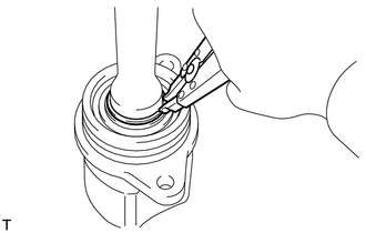
Using a snap ring expander, install a new snap ring.
Note
The Snap ring should be installed completely.
-
-
-
INSTALL FRONT DRIVE SHAFT DUST COVER (for RH Side)
-
w/o Drive Shaft Bearing Case:
-
Using SST and a press, install a new drive shaft dust cover to the front drive inboard joint assembly RH.
- SST
- 09527-10011
- 09726-40010
Standard distance (A) 41.6 to 42.6 mm (1.638 to 1.677 in.) Note
-
Make sure to install the front drive shaft dust cover in the correct direction.
-
Do not damage the front drive shaft dust cover.
-
The front drive shaft dust cover should be installed completely.
-
-
w/ Drive Shaft Bearing Case:
-
Using SST and a press, install a new drive shaft dust cover to the front drive inboard joint assembly RH.
- SST
- 09527-10011
- 09726-40010
Standard distance (A) 41.6 to 42.6 mm (1.638 to 1.677 in.) Note
-
Make sure to install the front drive shaft dust cover in the correct direction.
-
Do not damage the front drive shaft dust cover.
-
The front drive shaft dust cover should be installed completely.
-
-
-
INSTALL FRONT DRIVE SHAFT DUST COVER LH
-
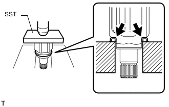
Using SST and a press, press in the front drive inboard joint assembly LH until the new front drive shaft dust cover LH contacts the edge of the front drive inboard joint assembly LH.
- SST
- 09527-10011
Note
-
Make sure to install the front drive shaft dust cover LH in the correct direction.
-
Do not damage the front drive shaft dust cover LH.
-
The front drive shaft dust cover LH should be installed completely.
-
-
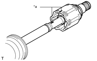
INSTALL FRONT DRIVE SHAFT DUST COVER RH
-
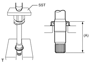
Using SST and a press, install a new front drive shaft dust cover RH to the front drive inboard joint assembly RH until the distance from the tip of the front drive inboard joint assembly RH to the front drive shaft dust cover RH onto reaches the specification as shown in the illustration.
- SST
- 09527-10011
Standard Distance (A) Item Length for 1AD-FTV (Manual Transaxle) 110.0 to 111.0 mm (4.331 to 4.370 in.) for 2AR-FE (Automatic Transaxle) for 2AR-FE (Manual Transaxle) 91.0 to 92.0 mm (3.583 to 3.622 in.) for 3ZR-FE (Manual Transaxle) for 3ZR-FE (CVT) Note
-
Make sure to install the front drive shaft dust cover RH in the correct direction.
-
Do not damage the front drive shaft dust cover RH.
-
Front drive shaft dust cover RH should be installed completely.
-
-
INSTALL FRONT AXLE OUTBOARD JOINT BOOT
Tech Tips
Use the same procedure for the RH and LH sides.
-
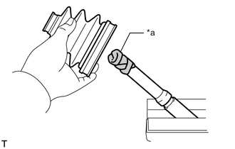
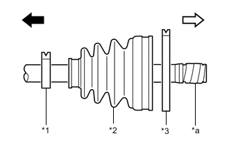
*a Protective Tape Before installing the front axle outboard joint boot, wrap the splines of the front drive outboard joint shaft assembly with protective tape to prevent the front axle outboard joint boot from being damaged.
-
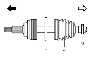
*1 Front No. 2 Axle Outboard Joint Boot Clamp *2 Front Axle Outboard Joint Boot *3 Front Axle Outboard Joint Boot Clamp 
Outboard Joint Side 
Inboard Joint Side Install new parts to the front drive outboard joint shaft assembly in the following order.
-
Front No. 2 axle outboard joint boot clamp
-
Front axle outboard joint boot
-
Front axle outboard joint boot clamp
-
-
Install the front axle outboard joint boot so that it is between the front No. 2 axle outboard joint boot clamp and front drive outboard joint shaft assembly.
-
Temporarily install the front axle outboard joint boot clamp to the front axle outboard joint boot.
-
Pack the front drive outboard joint shaft assembly and front axle outboard joint boot with grease from the boot kit.
Standard Grease Capacity Item Grease Capacity for 1AD-FTV (Manual Transaxle) 205 to 215 g (7.3 to 7.5 oz) for 2AR-FE (Automatic Transaxle) for 2AR-FE (Manual Transaxle) for 3ZR-FE (Manual Transaxle) for 3ZR-FE (CVT) 171 to 181 g (6.1 to 6.3 oz) -
Install the front axle outboard joint boot to the groove of the front drive outboard joint shaft assembly.
Note
-
Do not apply grease to the part of the front axle outboard joint boot that contacts the groove.
-
Do not allow foreign matter to enter the front axle outboard joint boot.
-
-
-
INSTALL FRONT NO. 2 AXLE OUTBOARD JOINT BOOT CLAMP LH
CAUTION:
Wear protective gloves to avoid injuries to your hands.
-
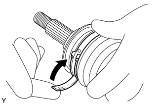
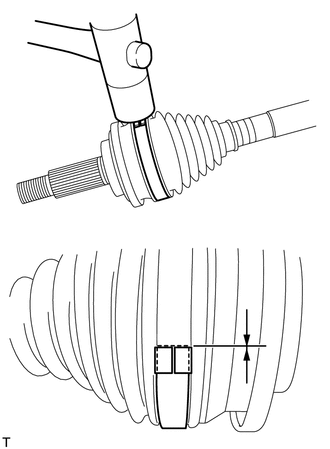
Install the front No. 2 axle outboard joint boot clamp LH onto the front axle outboard joint boot and temporarily fold back the lever.
Note
-
Set the lever into the guide groove correctly and install the front No. 2 axle outboard joint boot clamp LH as close to the inside of the vehicle as possible.
-
Check the band and lever for any deformation before folding back the lever.
-
-
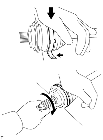
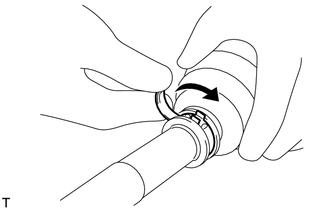
Lean your weight on your hand and roll the front drive outboard joint shaft assembly LH forward while pressing the front drive outboard joint shaft assembly LH against a surface until a click sound is heard.
Note
-
Do not damage the deflector.
-
Make sure that the front drive outboard joint shaft assembly LH is in direct contact with the surface.
-
-
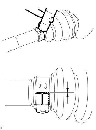
Using a plastic-faced hammer, tap the buckle to fix the lever in place while making sure that the end of the lever is even with the edge of the buckle.
Note
Do not damage the front axle outboard joint boot.
-
-
INSTALL FRONT NO. 2 AXLE OUTBOARD JOINT BOOT CLAMP RH
Tech Tips
Use the same procedure described for the LH side.
-
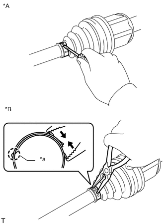
INSTALL FRONT AXLE OUTBOARD JOINT BOOT CLAMP LH
CAUTION:
Wear protective gloves to avoid injuries to your hands.
-
Install the front axle outboard joint boot clamp LH to the front axle outboard joint boot and temporarily fold back the lever.
Note
-
Set the lever into the guide groove correctly.
-
Check the band and lever for any deformation before folding back the lever.
-
-
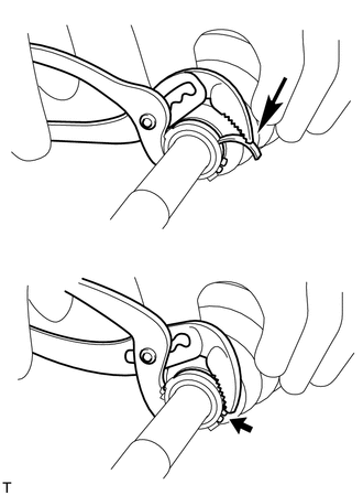
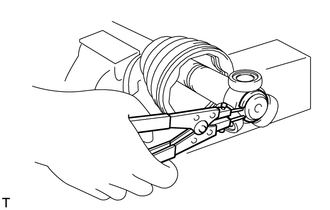
Using water pump pliers, pinch the front axle outboard joint boot clamp LH to temporarily fix it in place.
-
Using a plastic-faced hammer, tap the buckle to fix the lever in place while making sure that the end of the lever is even with the edge of the buckle.
Note
Do not damage the front axle outboard joint boot.
-
-
INSTALL FRONT AXLE OUTBOARD JOINT BOOT CLAMP RH
Tech Tips
Use the same procedure described for the LH side.
-
INSTALL FRONT DRIVE SHAFT DAMPER LH (w/ Drive Shaft Damper)
-
w/ 1 Clamp:
-
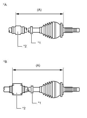
*A for 3ZR-FE *B except 3ZR-FE *1 Front Drive Shaft Damper Clamp LH *2 Front Drive Shaft Damper LH Install a new front drive shaft damper clamp LH and front drive shaft damper LH onto the front drive outboard joint shaft assembly LH.
Tech Tips
Make sure the front drive shaft damper clamp LH is on the outboard joint side.
-
Adjust the position of the drive shaft damper LH so that the distance shown in the illustration is within the specified range.
Standard Distance (A) Item Length for 3ZR-FE 199.0 to 203.0 mm (7.835 to 7.992 in.) except 3ZR-FE 212.5 to 216.5 mm (8.367 to 8.523 in.)
-
-
w/ 2 Clamps:
-
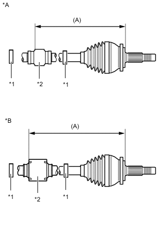
*A for 3ZR-FE *B except 3ZR-FE *1 Front Drive Shaft Damper Clamp LH *2 Front Drive Shaft Damper LH Install 2 new front drive shaft damper clamp LH and the front drive shaft damper LH onto the front drive outboard joint shaft assembly LH.
-
Adjust the position of the drive shaft damper LH so that the distance shown in the illustration is within the specified range.
Standard Distance (A) Item Length for 3ZR-FE 199.0 to 203.0 mm (7.835 to 7.992 in.) except 3ZR-FE 212.5 to 216.5 mm (8.367 to 8.523 in.)
-
-
-
INSTALL FRONT DRIVE SHAFT DAMPER RH (w/ Drive Shaft Damper)
-
w/ 1 Clamp:
-
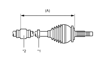
*1 Front Drive Shaft Damper Clamp RH *2 Front Drive Shaft Damper RH Install a new front drive shaft damper clamp RH and front drive shaft damper RH onto the front drive outboard joint shaft assembly RH.
Tech Tips
Make sure the front drive shaft damper clamp RH is on the outboard joint side.
-
Adjust the position of the drive shaft damper RH so that the distance shown in the illustration is within the specified range.
Standard Distance (A) 199.0 to 203.0 mm (7.835 to 7.992 in.)
-
-
w/ 2 Clamps:
-
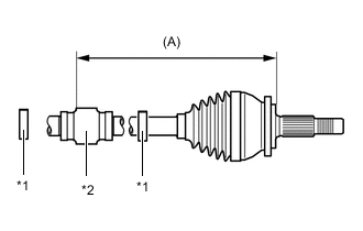
*1 Front Drive Shaft Damper Clamp RH *2 Front Drive Shaft Damper RH Install 2 new front drive shaft damper clamp RH and the front drive shaft damper RH onto the front drive outboard joint shaft assembly RH.
-
Adjust the position of the drive shaft damper RH so that the distance shown in the illustration is within the specified range.
Standard Distance (A) 199.0 to 203.0 mm (7.835 to 7.992 in.)
-
-
-
INSTALL FRONT DRIVE SHAFT DAMPER CLAMP LH (w/ Drive Shaft Damper)
-
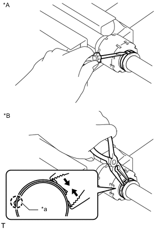
*A for One Touch Type *B for Claw Engagement Type *a Claw Engagement w/ 1 Clamp:
Install the front drive shaft damper clamp LH.
Note
Be sure to install the front drive shaft damper clamp LH in the correct position.
-
for One Touch Type:
Using a screwdriver, install the front drive shaft damper clamp LH as shown in the illustration.
-
for Claw Engagement Type:
Using needle-nose pliers, install the front drive shaft damper clamp LH as shown in the illustration.
Note
Do not deform the claw engagement of the front drive shaft damper clamp LH.
-
-
*A for One Touch Type *B for Claw Engagement Type *a Claw Engagement w/ 2 Clamps:
Install the 2 front drive shaft damper clamp LH.
Note
Be sure to install the front drive shaft damper clamp LH in the correct position.
-
for One Touch Type:
Using a screwdriver, install the 2 front drive shaft damper clamp LH as shown in the illustration.
-
for Claw Engagement Type:
Using needle-nose pliers, hold the 2 front drive shaft damper clamp LH at the claw engagement.
Note
Do not deform the claw engagement of the front drive shaft damper clamp LH.
-
-
-
INSTALL FRONT DRIVE SHAFT DAMPER CLAMP RH (w/ Drive Shaft Damper)
Tech Tips
Use the same procedure described for the LH side.
-
INSTALL FRONT DRIVE INBOARD JOINT ASSEMBLY LH
-
*1 Front Axle Inboard Joint Boot Clamp LH *2 Front Axle Inboard Joint Boot *3 Front No. 2 Axle Inboard Joint Boot Clamp LH *a Protective Tape Outboard Joint Side Inboard Joint Side Install new parts to the front drive outboard joint shaft assembly LH in the following order.
-
Front axle inboard joint boot clamp LH
-
Front axle inboard joint boot
-
Front No. 2 axle inboard joint boot clamp LH
-
-
Remove the protective tape from the front drive outboard joint shaft assembly LH.
-
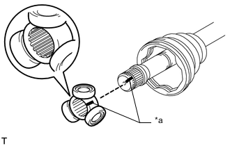
*a Matchmark Align the matchmarks and place the beveled side of the tripod joint axial spline toward the front drive outboard joint shaft assembly LH.
Note
Face the cut edge of the spline toward the inboard joint side and insert the spline onto the outboard joint shaft assembly LH.
-
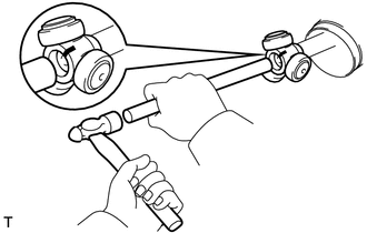
Using a brass bar and hammer, tap the tripod joint onto the front drive outboard joint shaft assembly LH.
Note
-
Do not tap the rollers.
-
Be sure to install the tripod in the correct direction.
-
-
Using a snap ring expander, install a new snap ring.
Note
The Snap ring should be installed completely.
-
Pack the front drive inboard joint assembly LH and front axle inboard joint boot with grease from the boot kit.
Standard grease capacity 175 to 185 g (6.2 to 6.5 oz) -
*a Matchmark Align the matchmarks and install the front drive inboard joint assembly LH to the front drive outboard joint shaft assembly LH.
-
-
INSTALL FRONT DRIVE INBOARD JOINT ASSEMBLY RH
Tech Tips
Use the same procedure described for the LH side.
-
INSTALL FRONT AXLE INBOARD JOINT BOOT
Tech Tips
Use the same procedure for the RH and LH sides.
-
Install the front axle inboard joint boot to the front drive inboard joint assembly.
Note
-
Do not apply grease to the part of the front axle inboard joint boot that contacts the groove.
-
Do not allow foreign matter to enter the front axle inboard joint boot.
-
-
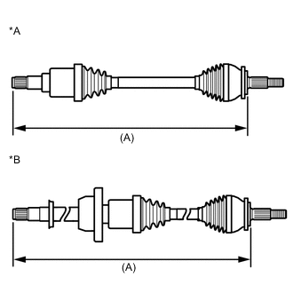
*A for LH Side *B for RH Side Check that the front axle inboard joint boot and front axle outboard joint boot are not stretched or contracted when the rear drive shaft assembly is at the standard length.
Length (A) Item Length for 1AD-FTV (Manual Transaxle) LH Side 553.6 mm (1.82 ft.) RH Side 932.4 mm (3.06 ft.) for 2AR-FE (Automatic Transaxle) LH Side 577.6 mm (1.89 ft.) RH Side 914.4 mm (3.00 ft.) for 2AR-FE (Manual Transaxle) LH Side 583.6 mm (1.91 ft.) RH Side 906.4 mm (2.97 ft.) for 3ZR-FE (Manual Transaxle) LH Side 594.6 mm (1.95 ft.) RH Side 893.4 mm (2.93 ft.) for 3ZR-FE (CVT) LH Side 591.2 mm (1.94 ft.) RH Side 890.0 mm (2.92 ft.) Note
Keep the drive shaft assembly level during inspection.
If the front axle inboard joint boot and front axle outboard joint boot are stretched or contracted, correct them.
-
-
INSTALL FRONT AXLE INBOARD JOINT BOOT CLAMP LH
-
*A for One Touch Type *B for Claw Engagement Type *a Claw Engagement for One Touch Type:
Using a screwdriver, install the front axle inboard joint boot clamp LH as shown in the illustration.
Note
-
Correctly set the front axle inboard joint boot clamp LH to the guide groove.
-
Do not damage the front axle inboard joint boot.
-
-
for Claw Engagement Type:
-
Install the front axle inboard joint boot clamp LH to the drive shaft inboard joint boot.
Note
Correctly set the front axle inboard joint boot clamp LH to the guide groove.
-
Using needle-nose pliers, hold the front axle inboard joint boot clamp LH at the claw engagement.
Note
-
Do not damage the front axle inboard joint boot.
-
Do not deform the claw engagement of the front axle inboard joint boot clamp LH.
-
-
-
-
INSTALL FRONT AXLE INBOARD JOINT BOOT CLAMP RH
Tech Tips
Use the same procedure described for the LH side.
-
INSTALL FRONT NO. 2 AXLE INBOARD JOINT BOOT CLAMP LH
Tech Tips
Use the same procedure described for the front axle inboard joint boot clamp LH.
-
INSTALL FRONT NO. 2 AXLE INBOARD JOINT BOOT CLAMP RH
Tech Tips
Use the same procedure described for the LH side.
-
INSPECT FRONT DRIVE SHAFT