TRANSFER ASSEMBLY REASSEMBLY

CAUTION / NOTICE / HINT
Note
Steps 9 to 16 are temporary reassembly procedures for adjustment purposes.
PROCEDURE
-
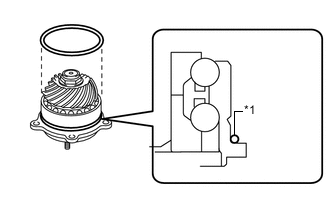
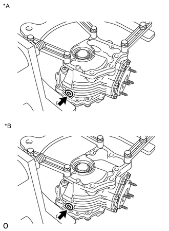
INSTALL BREATHER OIL DEFLECTOR
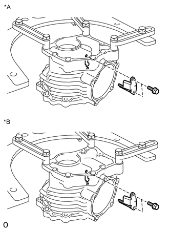
*A for CVT *B for Automatic Transaxle and Manual Transaxle
-
Install a new breather oil deflector to the transfer case with the 2 bolts.
- Torque:
- 6.5 N*m { 66 kgf*cm, 58 in.*lbf }
-
-
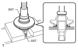
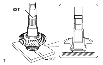
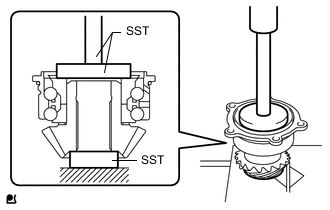
INSTALL TRANSFER RING GEAR MOUNTING CASE
-
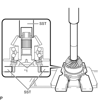
Using SST and a press, press the transfer ring gear mounting case into the transfer ring gear.
- SST
- 09316-12010
- 09950-60010 ( 09951-00560 )
Note
Do not put stress on the teeth of the transfer ring gear.
-
-
INSTALL SHAFT SNAP RING
-
Using a snap ring expander, install a new shaft snap ring.
-
-
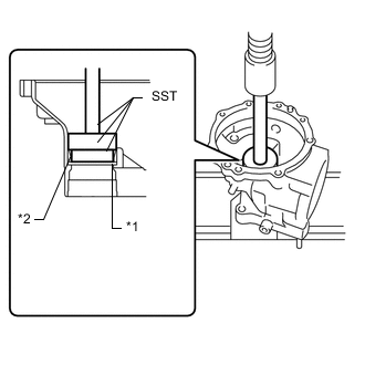
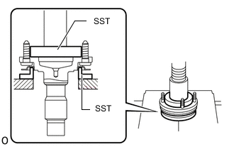
INSTALL RING GEAR MOUNTING CASE BEARING RH
-
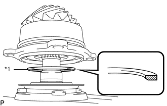
*1 No. 2 Transfer Ring Gear Mounting Case Washer *2 Ring Gear Mounting Case Bearing RH (Outer Race) Install a new No. 2 transfer ring gear mounting case washer to the No. 1 transfer case cover.
Tech Tips
Install a No. 2 transfer ring gear mounting case washer with the same thickness as the one before the disassembly.
-
Using SST and a press, press the ring gear mounting case bearing RH (outer race) into the No. 1 transfer case cover.
- SST
- 09950-60020 ( 09951-00750, 09952-06010 )
- 09950-70010 ( 09951-07150 )
- 09951-00850
Note
-
Press in the ring gear mounting case bearing RH (outer race) and No. 2 transfer ring gear mounting case washer until they fit to the edge.
-
Do not put stress on the rolling contact surface of the ring gear mounting case bearing RH (outer race).
-
Using SST and a press, press the ring gear mounting case bearing RH (inner race) into the transfer ring gear mounting case.
- SST
- 09950-60010 ( 09951-00440, 09951-00650 )
Note
Do not deform the ring gear mounting case bearing RH (inner race) cage.
Tech Tips
When reusing the ring gear mounting case bearing RH, coat the ring gear mounting case bearing RH with Toyota Genuine Differential gear oil LT API GL-5 or equivalent.
-
-
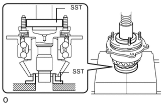
INSTALL RING GEAR MOUNTING CASE BEARING LH
-
*1 No. 1 Ring Gear Mounting Case Washer *2 Ring Gear Mounting Case Bearing LH (Outer Race) Install a new No. 1 ring gear mounting case washer to the transfer case.
Tech Tips
Install a No. 1 ring gear mounting case washer with the same thickness as the one before the disassembly.
-
Using SST and a press, press the ring gear mounting case bearing LH (outer race) into the transfer case.
for CVT:
- SST
- 09950-60010 ( 09951-00540, 09951-00610, 09952-06010 )
- 09950-70010 ( 09951-07150 )
for Automatic Transaxle and Manual Transaxle:
- SST
- 09950-60010 ( 09951-00570, 09951-00650, 09952-06010 )
- 09950-70010 ( 09951-07150 )
Note
-
Press in the ring gear mounting case bearing LH (outer race) and No. 1 ring gear mounting case washer until they fit to the edge.
-
Do not put stress on the rolling contact surface of the ring gear mounting case bearing LH (outer race).
-
Using SST and a press, press the ring gear mounting case bearing LH (inner race) into the transfer ring gear mounting case.
- SST
- 09336-16010
- 09950-60010 ( 09951-00560 )
Note
Do not deform the ring gear mounting case bearing LH (inner race) cage.
Tech Tips
When reusing the ring gear mounting case bearing LH, coat the ring gear mounting case bearing LH with Toyota Genuine Differential gear oil LT API GL-5 or equivalent.
-
-
INSTALL TRANSFER OUTPUT SHAFT WASHER
-
Install the transfer output shaft washer to the transfer driven pinion.
-
-
INSTALL FRONT TRANSFER DRIVEN PINION BEARING
-
w/o Washer:
-
Using SST and a press, press the front transfer driven pinion bearing into the transfer driven pinion.
- SST
- 09950-60010 ( 09951-00440, 09951-00550 )
- 09950-70010 ( 09951-07150 )
Note
Do not apply stress to any parts of the front transfer driven pinion bearing inner race or transfer driven pinion other than the flat surfaces.
-
-
w/ Washer:
Note
-
The front transfer driven pinion bearing service kit consists of a front transfer driven pinion bearing and washer.
-
The supplied washer is used in the transfer driven pinion installation procedure.
-
Using SST and a press, press the front transfer driven pinion bearing into the transfer driven pinion.
- SST
- 09950-60010 ( 09951-00440, 09951-00550 )
- 09950-70010 ( 09951-07150 )
Note
Do not apply stress to any parts of the front transfer driven pinion bearing inner race or transfer driven pinion other than the flat surfaces.
-
-
-
INSTALL REAR TRANSFER OUTPUT SHAFT DUST DEFLECTOR
-
Using SST and a press, press a new rear transfer output shaft dust deflector into the rear transfer output shaft sub-assembly.
- SST
- 09316-12010
- 09950-60020 ( 09951-00680 )
Note
The rear transfer output shaft dust deflector should be installed completely.
-
-
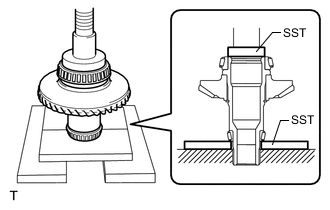
INSTALL TRANSFER DRIVEN PINION
-
w/o Washer:
-
Using SST and a press, press the rear transfer output shaft sub-assembly into the transfer driven pinion.
- SST
- 09506-30012
- 09950-60020 ( 09951-00680 )
Note
Do not apply stress to any parts of the transfer output shaft flange or transfer driven pinion other than the flat surfaces.
-
Secure the rear transfer output shaft sub-assembly in a vise between aluminum plates.
Note
Do not overtighten the vise.
-
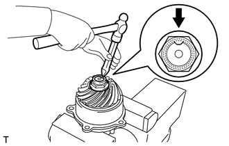
Using a 30 mm socket wrench, install a new transfer gear nut to the rear transfer output shaft sub-assembly.
- Torque:
- 360 N*m { 3671 kgf*cm, 266 ft.*lbf }
-
-
*1 Washer w/ Washer:
Note
The front transfer driven pinion bearing service kit consists of a front transfer driven pinion bearing and washer.
-
Install the washer to the rear transfer output shaft sub-assembly as shown in the illustration.
Note
Install the washer in the correct direction.
-
*1 Washer Using SST and a press, press the transfer driven pinion into the rear transfer output shaft sub-assembly.
- SST
- 09608-04031
Note
Do not apply stress to any parts of the transfer output shaft flange or transfer driven pinion other than the flat surfaces.
-
Secure the rear transfer output shaft sub-assembly in a vise between aluminum plates.
Note
Do not overtighten the vise.
-
Using a 30 mm socket wrench, temporarily tighten a new transfer gear nut to the rear transfer output shaft sub-assembly.
-
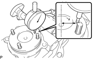
*a 30 mm (1.18 in.) Using a dial indicator, measure the runout at the rear transfer output shaft sub-assembly flange.
Maximum runout 0.064 mm (0.00252 in.) If the runout is more than the maximum, remove and reinstall the rear transfer output shaft sub-assembly.
-
Using a dial indicator, measure the runout at the inner side of the rear transfer output shaft sub-assembly flange.
Maximum runout 0.063 mm (0.00248 in.) If the runout is more than the maximum, remove and reinstall the rear transfer output shaft sub-assembly.
-
Using a 30 mm socket wrench, fully tighten the transfer gear nut to the rear transfer output shaft sub-assembly.
- Torque:
- 360 N*m { 3671 kgf*cm, 266 ft.*lbf }
-
-
-
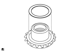
INSTALL REAR TRANSFER OUTPUT SHAFT SUB-ASSEMBLY
-
*1 O-ring Install a new O-ring to the front transfer driven pinion bearing.
Note
-
Do not scratch or twist the O-ring.
-
Firmly install the O-ring into the groove of the front transfer driven pinion bearing.
-
-
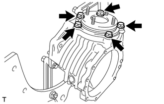
Install the rear transfer output shaft sub-assembly to the transfer case with the 5 bolts.
- Torque:
- 38 N*m { 387 kgf*cm, 28 ft.*lbf }
Note
Do not scratch or twist the O-ring.
-
-
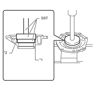
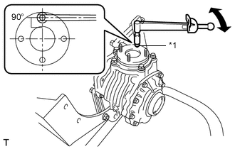
INSPECT DRIVEN PINION PRELOAD
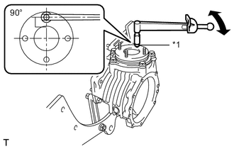
*1 Nut
-
Install a nut to the stud bolt.
Tech Tips
Use a nut that is used for installing the propeller shaft.
-
Using a torque wrench, check the driven pinion preload (starting torque) of the driven pinion.
Driven pinion preload (starting torque) Item Specified Condition New bearing 0.28 to 2.04 N*m (2.86 to 20.80 kgf*cm, 2.48 to 18.05 in.*lbf) Reused bearing 0.24 to 1.39 N*m (2.45 to 14.17 kgf*cm, 2.13 to 12.30 in.*lbf) Note
Measure the preload after rotating the bearing several times in the forward and backward directions to make sure the bearing is operating correctly.
Tech Tips
Install the torque wrench as shown in the illustration.
-
-
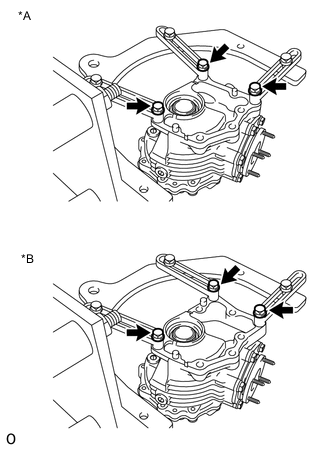
INSTALL TRANSFER RING GEAR
-
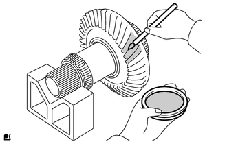
Uniformly apply a light coat of Prussian Blue on both sides of the transfer ring gear teeth.
-
Install the transfer ring gear to the transfer case.
-
-
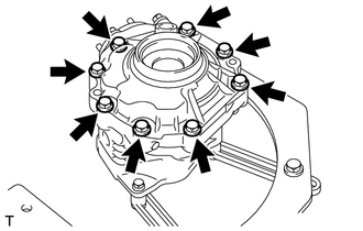
INSTALL NO. 1 TRANSFER CASE COVER
-
Install the No. 1 transfer case cover to the transfer case with the 8 bolts.
- Torque:
- 47 N*m { 479 kgf*cm, 35 ft.*lbf }
-
-
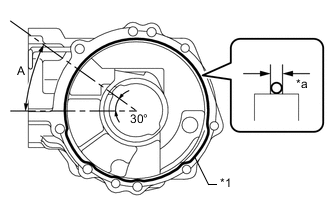
ADJUST RING GEAR BACKLASH
-
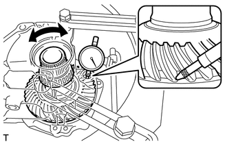
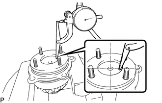
Insert a dial indicator into the No. 2 transfer case plug hole, and place it perpendicular to the edge of a transfer ring gear tooth.
-
While securing the rear transfer output shaft sub-assembly by hand, rotate the transfer ring gear mounting case forward and backward by hand and measure the backlash of the transfer ring gear and transfer driven pinion.
Standard backlash 0.10 to 0.20 mm (0.00394 to 0.00787 in.) Note
Measure the ring gear at 3 or more locations.
-
If the result is not within the specified range, select a No. 1 ring gear mounting case washer (for backlash adjustment) and a No. 2 transfer ring gear mounting case washer (for preload adjustment) from the table below and reinstall them to bring the result within the specified range.
Tech Tips
-
If the backlash is small, select a thick washer for the No. 1 ring gear mounting case washer (for backlash adjustment) and a thin washer for the No. 2 transfer ring gear mounting case washer (for preload adjustment).
-
If the backlash is large, select a thin washer for the No. 1 ring gear mounting case washer (for backlash adjustment) and a thick washer for the No. 2 transfer ring gear mounting case washer (for preload adjustment).
No. 1 Ring Gear Mounting Case Washer (for backlash adjustment) for CVT Part No. Thickness Identifying Mark Part No. Thickness Identifying Mark 36265-52010 1.96 to 1.98 mm (0.0772 to 0.0779 in.) A0 36265-52210 2.36 to 2.38 mm (0.0930 to 0.0937 in.) C0 36265-52020 1.98 to 2.00 mm (0.0780 to 0.0787 in.) A1 36265-52220 2.38 to 2.40 mm (0.0938 to 0.0944 in.) C1 36265-52030 2.00 to 2.02 mm (0.0788 to 0.0795 in.) A2 36265-52230 2.40 to 2.42 mm (0.0945 to 0.0952 in.) C2 36265-52040 2.02 to 2.04 mm (0.0796 to 0.0803 in.) A3 36265-52240 2.42 to 2.44 mm (0.0953 to 0.0960 in.) C3 36265-52050 2.04 to 2.06 mm (0.0804 to 0.0811 in.) A4 36265-52250 2.44 to 2.46 mm (0.0961 to 0.0968 in.) C4 36265-52060 2.06 to 2.08 mm (0.0812 to 0.0818 in.) A5 36265-52260 2.46 to 2.48 mm (0.0969 to 0.0976 in.) C5 36265-52070 2.08 to 2.10 mm (0.0819 to 0.0826 in.) A6 36265-52270 2.48 to 2.50 mm (0.0977 to 0.0984 in.) C6 36265-52080 2.10 to 2.12 mm (0.0827 to 0.0834 in.) A7 36265-52280 2.50 to 2.52 mm (0.0985 to 0.0992 in.) C7 36265-52090 2.12 to 2.14 mm (0.0835 to 0.0842 in.) A8 36265-52290 2.52 to 2.54 mm (0.0993 to 0.0999 in.) C8 36265-52100 2.14 to 2.16 mm (0.0843 to 0.0850 in.) A9 36265-52300 2.54 to 2.56 mm (0.1000 to 0.1007 in.) C9 36265-52110 2.16 to 2.18 mm (0.0851 to 0.0858 in.) B0 36265-52310 2.56 to 2.58 mm (0.1008 to 0.1015 in.) D0 36265-52120 2.18 to 2.20 mm (0.0859 to 0.0866 in.) B1 36265-52320 2.58 to 2.60 mm (0.1016 to 0.1023 in.) D1 36265-52130 2.20 to 2.22 mm (0.0867 to 0.0874 in.) B2 36265-52330 2.60 to 2.62 mm (0.1024 to 0.1031 in.) D2 36265-52140 2.22 to 2.24 mm (0.0875 to 0.0881 in.) B3 36265-52340 2.62 to 2.64 mm (0.1032 to 0.1039 in.) D3 36265-52150 2.24 to 2.26 mm (0.0882 to 0.0889 in.) B4 36265-52350 2.64 to 2.66 mm (0.1040 to 0.1047 in.) D4 36265-52160 2.26 to 2.28 mm (0.0890 to 0.0897 in.) B5 36265-52360 2.66 to 2.68 mm (0.1048 to 0.1055 in.) D5 36265-52170 2.28 to 2.30 mm (0.0898 to 0.0905 in.) B6 36265-52370 2.68 to 2.70 mm (0.1056 to 0.1062 in.) D6 36265-52180 2.30 to 2.32 mm (0.0906 to 0.0913 in.) B7 36265-52380 2.70 to 2.72 mm (0.1063 to 0.1070 in.) D7 36265-52190 2.32 to 2.34 mm (0.0914 to 0.0921 in.) B8 36265-52390 2.72 to 2.74 mm (0.1071 to 0.1078 in.) D8 36265-52200 2.34 to 2.36 mm (0.0922 to 0.0929 in.) B9 36265-52400 2.74 to 2.76 mm (0.1079 to 0.1086 in.) D9 No. 1 Ring Gear Mounting Case Washer (for backlash adjustment) for Automatic Transaxle and Manual Transaxle Part No. Thickness Identifying Mark Part No. Thickness Identifying Mark 36265-42010 1.96 to 1.98 mm (0.0772 to 0.0779 in.) A0 36265-42210 2.36 to 2.38 mm (0.0930 to 0.0937 in.) C0 36265-42020 1.98 to 2.00 mm (0.0780 to 0.0787 in.) A1 36265-42220 2.38 to 2.40 mm (0.0938 to 0.0944 in.) C1 36265-42030 2.00 to 2.02 mm (0.0788 to 0.0795 in.) A2 36265-42230 2.40 to 2.42 mm (0.0945 to 0.0952 in.) C2 36265-42040 2.02 to 2.04 mm (0.0796 to 0.0803 in.) A3 36265-42240 2.42 to 2.44 mm (0.0953 to 0.0960 in.) C3 36265-42050 2.04 to 2.06 mm (0.0804 to 0.0811 in.) A4 36265-42250 2.44 to 2.46 mm (0.0961 to 0.0968 in.) C4 36265-42060 2.06 to 2.08 mm (0.0812 to 0.0818 in.) A5 36265-42260 2.46 to 2.48 mm (0.0969 to 0.0976 in.) C5 36265-42070 2.08 to 2.10 mm (0.0819 to 0.0826 in.) A6 36265-42270 2.48 to 2.50 mm (0.0977 to 0.0984 in.) C6 36265-42080 2.10 to 2.12 mm (0.0827 to 0.0834 in.) A7 36265-42280 2.50 to 2.52 mm (0.0985 to 0.0992 in.) C7 36265-42090 2.12 to 2.14 mm (0.0835 to 0.0842 in.) A8 36265-42290 2.52 to 2.54 mm (0.0993 to 0.0999 in.) C8 36265-42100 2.14 to 2.16 mm (0.0843 to 0.0850 in.) A9 36265-42300 2.54 to 2.56 mm (0.1000 to 0.1007 in.) C9 36265-42110 2.16 to 2.18 mm (0.0851 to 0.0858 in.) B0 36265-42310 2.56 to 2.58 mm (0.1008 to 0.1015 in.) D0 36265-42120 2.18 to 2.20 mm (0.0859 to 0.0866 in.) B1 36265-42320 2.58 to 2.60 mm (0.1016 to 0.1023 in.) D1 36265-42130 2.20 to 2.22 mm (0.0867 to 0.0874 in.) B2 36265-42330 2.60 to 2.62 mm (0.1024 to 0.1031 in.) D2 36265-42140 2.22 to 2.24 mm (0.0875 to 0.0881 in.) B3 36265-42340 2.62 to 2.64 mm (0.1032 to 0.1039 in.) D3 36265-42150 2.24 to 2.26 mm (0.0882 to 0.0889 in.) B4 36265-42350 2.64 to 2.66 mm (0.1040 to 0.1047 in.) D4 36265-42160 2.26 to 2.28 mm (0.0890 to 0.0897 in.) B5 36265-42360 2.66 to 2.68 mm (0.1048 to 0.1055 in.) D5 36265-42170 2.28 to 2.30 mm (0.0898 to 0.0905 in.) B6 36265-42370 2.68 to 2.70 mm (0.1056 to 0.1062 in.) D6 36265-42180 2.30 to 2.32 mm (0.0906 to 0.0913 in.) B7 36265-42380 2.70 to 2.72 mm (0.1063 to 0.1070 in.) D7 36265-42190 2.32 to 2.34 mm (0.0914 to 0.0921 in.) B8 36265-42390 2.72 to 2.74 mm (0.1071 to 0.1078 in.) D8 36265-42200 2.34 to 2.36 mm (0.0922 to 0.0929 in.) B9 36265-42400 2.74 to 2.76 mm (0.1079 to 0.1086 in.) D9 No. 2 Transfer Ring Gear Mounting Case Washer (for preload adjustment) Part No. Thickness Identifying Mark Part No. Thickness Identifying Mark 36266-52010 1.17 to 1.19 mm (0.0461 to 0.0468 in.) A0 36266-52230 1.61 to 1.63 mm (0.0634 to 0.0641 in.) C2 36266-52020 1.19 to 1.21 mm (0.0469 to 0.0476 in.) A1 36266-52240 1.63 to 1.65 mm (0.0642 to 0.0649 in.) C3 36266-52030 1.21 to 1.23 mm (0.0477 to 0.0484 in.) A2 36266-52250 1.65 to 1.67 mm (0.0650 to 0.0657 in.) C4 36266-52040 1.23 to 1.25 mm (0.0485 to 0.0492 in.) A3 36266-52260 1.67 to 1.69 mm (0.0658 to 0.0665 in.) C5 36266-52050 1.25 to 1.27 mm (0.0493 to 0.0499 in.) A4 36266-52270 1.69 to 1.71 mm (0.0666 to 0.0673 in.) C6 36266-52060 1.27 to 1.29 mm (0.0500 to 0.0507 in.) A5 36266-52280 1.71 to 1.73 mm (0.0674 to 0.0681 in.) C7 36266-52070 1.29 to 1.31 mm (0.0508 to 0.0515 in.) A6 36266-52290 1.73 to 1.75 mm (0.0682 to 0.0688 in.) C8 36266-52080 1.31 to 1.33 mm (0.0516 to 0.0523 in.) A7 36266-52300 1.75 to 1.77 mm (0.0689 to 0.0696 in.) C9 36266-52090 1.33 to 1.35 mm (0.0524 to 0.0531 in.) A8 36266-52310 1.77 to 1.79 mm (0.0697 to 0.0704 in.) D0 36266-52100 1.35 to 1.37 mm (0.0532 to 0.0539 in.) A9 36266-52320 1.79 to 1.81 mm (0.0705 to 0.0712 in.) D1 36266-52110 1.37 to 1.39 mm (0.0540 to 0.0547 in.) B0 36266-52330 1.81 to 1.83 mm (0.0713 to 0.0720 in.) D2 36266-52120 1.39 to 1.41 mm (0.0548 to 0.0555 in.) B1 36266-52340 1.83 to 1.85 mm (0.0721 to 0.0728 in.) D3 36266-52130 1.41 to 1.43 mm (0.0556 to 0.0562 in.) B2 36266-52350 1.85 to 1.87 mm (0.0729 to 0.0736 in.) D4 36266-52140 1.43 to 1.45 mm (0.0563 to 0.0570 in.) B3 36266-52360 1.87 to 1.89 mm (0.0737 to 0.0744 in.) D5 36266-52150 1.45 to 1.47 mm (0.0571 to 0.0578 in.) B4 36266-52370 1.89 to 1.91 mm (0.0745 to 0.0751 in.) D6 36266-52160 1.47 to 1.49 mm (0.0579 to 0.0586 in.) B5 36266-52380 1.91 to 1.93 mm (0.0752 to 0.0759 in.) D7 36266-52170 1.49 to 1.51 mm (0.0587 to 0.0594 in.) B6 36266-52390 1.93 to 1.95 mm (0.0760 to 0.0767 in.) D8 36266-52180 1.51 to 1.53 mm (0.0595 to 0.0602 in.) B7 36266-52400 1.95 to 1.97 mm (0.0768 to 0.0775 in.) D9 36266-52190 1.53 to 1.55 mm (0.0603 to 0.0610 in.) B8 36266-52410 1.97 to 1.99 mm (0.0776 to 0.0783 in.) E0 36266-52200 1.55 to 1.57 mm (0.0611 to 0.0618 in.) B9 36266-52420 1.99 to 2.01 mm (0.0784 to 0.0791 in.) E1 36266-52210 1.57 to 1.59 mm (0.0619 to 0.0625 in.) C0 36266-52430 2.01 to 2.03 mm (0.0792 to 0.0799 in.) E2 36266-52220 1.59 to 1.61 mm (0.0626 to 0.0633 in.) C1 - - - -
-
-
ADJUST TOTAL PRELOAD
-
*1 Nut Install a nut to the stud bolt.
Tech Tips
Use a nut that is used for installing the propeller shaft.
-
Using a torque wrench, measure the total preload (starting torque) with the teeth of the driven pinion and ring gear in contact.
Total preload (starting torque) Item Specified Condition New bearing (with anti-rust oil) Driven pinion preload + 0.31 to 0.81 N*m (3.17 to 8.25 kgf*cm, 2.75 to 7.16 in.*lbf) Reused bearing (when coated with gear oil) Driven pinion preload + 0.23 to 0.81 N*m (2.35 to 8.25 kgf*cm, 2.04 to 7.16 in.*lbf) Note
Measure the preload after rotating the bearing several times in the forward and backward directions to make sure the bearing is operating correctly.
Tech Tips
Install the torque wrench as shown in the illustration.
-
If the result is not within the specified range, select a No. 2 transfer ring gear mounting case washer (for preload adjustment) from the table below and reinstall it to bring the result within the specified range.
Tech Tips
-
If the preload is small, select a thick washer for the No. 2 transfer ring gear mounting case washer (for preload adjustment).
-
If the preload is large, select a thin washer for the No. 2 transfer ring gear mounting case washer (for preload adjustment).
No. 2 Transfer Ring Gear Mounting Case Washer (for preload adjustment) Part No. Thickness Identifying Mark Part No. Thickness Identifying Mark 36266-52010 1.17 to 1.19 mm (0.0461 to 0.0468 in.) A0 36266-52230 1.61 to 1.63 mm (0.0634 to 0.0641 in.) C2 36266-52020 1.19 to 1.21 mm (0.0469 to 0.0476 in.) A1 36266-52240 1.63 to 1.65 mm (0.0642 to 0.0649 in.) C3 36266-52030 1.21 to 1.23 mm (0.0477 to 0.0484 in.) A2 36266-52250 1.65 to 1.67 mm (0.0650 to 0.0657 in.) C4 36266-52040 1.23 to 1.25 mm (0.0485 to 0.0492 in.) A3 36266-52260 1.67 to 1.69 mm (0.0658 to 0.0665 in.) C5 36266-52050 1.25 to 1.27 mm (0.0493 to 0.0499 in.) A4 36266-52270 1.69 to 1.71 mm (0.0666 to 0.0673 in.) C6 36266-52060 1.27 to 1.29 mm (0.0500 to 0.0507 in.) A5 36266-52280 1.71 to 1.73 mm (0.0674 to 0.0681 in.) C7 36266-52070 1.29 to 1.31 mm (0.0508 to 0.0515 in.) A6 36266-52290 1.73 to 1.75 mm (0.0682 to 0.0688 in.) C8 36266-52080 1.31 to 1.33 mm (0.0516 to 0.0523 in.) A7 36266-52300 1.75 to 1.77 mm (0.0689 to 0.0696 in.) C9 36266-52090 1.33 to 1.35 mm (0.0524 to 0.0531 in.) A8 36266-52310 1.77 to 1.79 mm (0.0697 to 0.0704 in.) D0 36266-52100 1.35 to 1.37 mm (0.0532 to 0.0539 in.) A9 36266-52320 1.79 to 1.81 mm (0.0705 to 0.0712 in.) D1 36266-52110 1.37 to 1.39 mm (0.0540 to 0.0547 in.) B0 36266-52330 1.81 to 1.83 mm (0.0713 to 0.0720 in.) D2 36266-52120 1.39 to 1.41 mm (0.0548 to 0.0555 in.) B1 36266-52340 1.83 to 1.85 mm (0.0721 to 0.0728 in.) D3 36266-52130 1.41 to 1.43 mm (0.0556 to 0.0562 in.) B2 36266-52350 1.85 to 1.87 mm (0.0729 to 0.0736 in.) D4 36266-52140 1.43 to 1.45 mm (0.0563 to 0.0570 in.) B3 36266-52360 1.87 to 1.89 mm (0.0737 to 0.0744 in.) D5 36266-52150 1.45 to 1.47 mm (0.0571 to 0.0578 in.) B4 36266-52370 1.89 to 1.91 mm (0.0745 to 0.0751 in.) D6 36266-52160 1.47 to 1.49 mm (0.0579 to 0.0586 in.) B5 36266-52380 1.91 to 1.93 mm (0.0752 to 0.0759 in.) D7 36266-52170 1.49 to 1.51 mm (0.0587 to 0.0594 in.) B6 36266-52390 1.93 to 1.95 mm (0.0760 to 0.0767 in.) D8 36266-52180 1.51 to 1.53 mm (0.0595 to 0.0602 in.) B7 36266-52400 1.95 to 1.97 mm (0.0768 to 0.0775 in.) D9 36266-52190 1.53 to 1.55 mm (0.0603 to 0.0610 in.) B8 36266-52410 1.97 to 1.99 mm (0.0776 to 0.0783 in.) E0 36266-52200 1.55 to 1.57 mm (0.0611 to 0.0618 in.) B9 36266-52420 1.99 to 2.01 mm (0.0784 to 0.0791 in.) E1 36266-52210 1.57 to 1.59 mm (0.0619 to 0.0625 in.) C0 36266-52430 2.01 to 2.03 mm (0.0792 to 0.0799 in.) E2 36266-52220 1.59 to 1.61 mm (0.0626 to 0.0633 in.) C1 - - - -
-
-
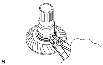
ADJUST TOOTH CONTACT BETWEEN RING GEAR AND DRIVE PINION
-
Rotate the transfer output shaft sub-assembly several times in the forward and backward directions.
-
Remove the transfer ring gear and check the tooth contact.
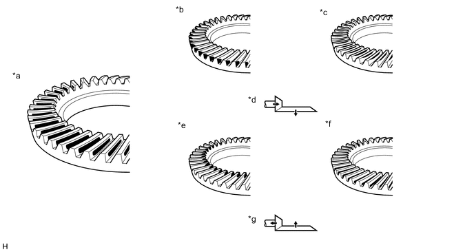
*a Proper Contact *b Heel Contact *c Face Contact *d Select an adjusting washer that will shift the drive pinion closer to the ring gear (*b, *c) *e Toe Contact *f Flank Contact *g Select an adjusting washer that will shift the drive pinion away from to the ring gear (*e, *f) - - Note
-
Check the tooth contact at 4 or more locations on the transfer ring gear.
-
When replacing washers (adjusting the backlash, preload or tooth contact pattern), reapply a coat of Prussian Blue.
Tech Tips
The Prussian Blue pattern indicates the tooth contact points.
-
-
In instances of face contact or flank contact, perform the following procedure.
-
Move and adjust the transfer ring gear using the No. 2 transfer ring gear mounting case washer (for preload adjustment) and the No. 1 ring gear mounting case washer (for backlash adjustment).
-
-
In instances of heel contact or toe contact, perform the following procedure.
-
Select a transfer output shaft washer (for tooth contact adjustment) from the table below, and move and adjust the transfer driven pinion.
Transfer Output Shaft Washer (for tooth contact adjustment) Part No. Thickness Identifying Mark Part No. Thickness Identifying Mark 36275-52010 1.01 to 1.03 mm (0.0398 to 0.0405 in.) 01 36275-52150 1.29 to 1.31 mm (0.0508 to 0.0515 in.) 15 36275-52020 1.03 to 1.05 mm (0.0406 to 0.0413 in.) 02 36275-52160 1.31 to 1.33 mm (0.0516 to 0.0523 in.) 16 36275-52030 1.05 to 1.07 mm (0.0414 to 0.0421 in.) 03 36275-52170 1.33 to 1.35 mm (0.0524 to 0.0531 in.) 17 36275-52040 1.07 to 1.09 mm (0.0422 to 0.0429 in.) 04 36275-52180 1.35 to 1.37 mm (0.0532 to 0.0539 in.) 18 36275-52050 1.09 to 1.11 mm (0.0430 to 0.0437 in.) 05 36275-52190 1.37 to 1.39 mm (0.0540 to 0.0547 in.) 19 36275-52060 1.11 to 1.13 mm (0.0438 to 0.0444 in.) 06 36275-52200 1.39 to 1.41 mm (0.0548 to 0.0555 in.) 20 36275-52070 1.13 to 1.15 mm (0.0445 to 0.0452 in.) 07 36275-52210 1.41 to 1.43 mm (0.0556 to 0.0562 in.) 21 36275-52080 1.15 to 1.17 mm (0.0453 to 0.0460 in.) 08 36275-52220 1.43 to 1.45 mm (0.0563 to 0.0570 in.) 22 36275-52090 1.17 to 1.19 mm (0.0461 to 0.0468 in.) 09 36275-52230 1.45 to 1.47 mm (0.0571 to 0.0578 in.) 23 36275-52100 1.19 to 1.21 mm (0.0469 to 0.0476 in.) 10 36275-52240 1.47 to 1.49 mm (0.0579 to 0.0586 in.) 24 36275-52110 1.21 to 1.23 mm (0.0477 to 0.0484 in.) 11 36275-52250 1.49 to 1.51 mm (0.0587 to 0.0594 in.) 25 36275-52120 1.23 to 1.25 mm (0.0485 to 0.0492 in.) 12 36275-52260 1.51 to 1.53 mm (0.0595 to 0.0602 in.) 26 36275-52130 1.25 to 1.27 mm (0.0493 to 0.0499 in.) 13 36275-52270 1.53 to 1.55 mm (0.0603 to 0.0610 in.) 27 36275-52140 1.27 to 1.29 mm (0.0500 to 0.0507 in.) 14 36275-52280 1.55 to 1.57 mm (0.0611 to 0.0618 in.) 28
-
-
If the tooth contact has been adjusted, recheck the backlash, preload and tooth contact pattern.
-
-
REMOVE NO. 1 TRANSFER CASE COVER
-
Remove the 8 bolts and No. 1 transfer case cover from the transfer case.
-
-
REMOVE TRANSFER RING GEAR
-
Remove the transfer ring gear from the transfer case.
-
-
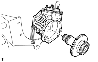
REMOVE REAR TRANSFER OUTPUT SHAFT SUB-ASSEMBLY
-
Remove the 5 bolts and rear transfer output shaft sub-assembly from the transfer case.
-
-
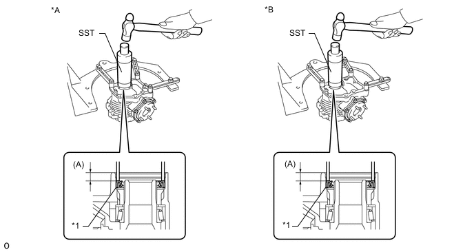
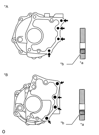
INSTALL TRANSFER CASE STRAIGHT PIN
-
Using a plastic-faced hammer, install straight pins to the locations shown in the illustration.
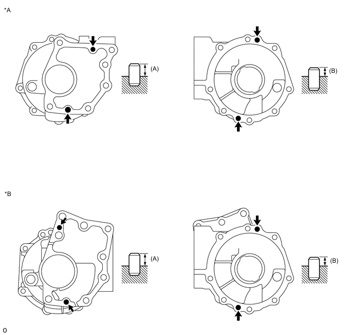
*A for CVT *B for Automatic Transaxle and Manual Transaxle Drive in depth (A) 10.8 to 11.8 mm (0.426 to 0.464 in.) Drive in depth (B) 6.5 to 7.5 mm (0.256 to 0.295 in.)
-
-
INSTALL REAR TRANSFER OUTPUT SHAFT SUB-ASSEMBLY
-
Secure the rear transfer output shaft sub-assembly in a vise between aluminum plates.
Note
Do not overtighten the vise.
-
Using a chisel and hammer, stake the transfer gear nut.
Note
Fully stake the transfer gear nut along the entire groove.
-
Install the rear transfer output shaft sub-assembly to the transfer case with the 5 bolts.
- Torque:
- 38 N*m { 387 kgf*cm, 28 ft.*lbf }
Note
Do not scratch, twist or break the O-ring.
-
-
INSTALL TRANSFER RING GEAR
-
Install the transfer ring gear to the transfer case.
-
-
INSTALL NO. 1 TRANSFER CASE COVER
-
Using a scraper, clean the seal packing from the transfer case and No. 1 transfer case cover and remove any oil using a cleaning solvent.
Note
Do not scratch the installation area.
-
*1 Seal Packing *a Seal Width 2.0 to 3.0 mm (0.0788 to 0.118 in.) Apply seal packing to the transfer case as shown in the illustration.
Seal packing Toyota Genuine Seal Packing 1281, Three Bond 1281 or equivalent Note
-
Install the cover to the case within 10 minutes of application.
-
Start the application from inside the area marked A.
-
Overlap the seal packing at least 10 mm (0.394 in.) at the beginning and the end of application.
-
-
Install the No. 1 transfer case cover with the 8 bolts.
- Torque:
- 47 N*m { 479 kgf*cm, 35 ft.*lbf }
-
-
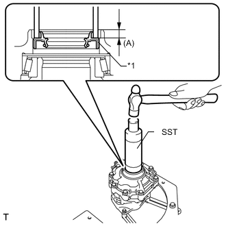
INSTALL TRANSFER CASE OIL SEAL
-
Using SST and a hammer, tap in a new transfer case oil seal as shown in the illustration.
- SST
- 09316-60011 ( 09316-00011 )
*A for CVT *B for Automatic Transaxle and Manual Transaxle *1 Transfer Case Oil Seal - - Drive in depth (A) 9.5 to 10.5 mm (0.375 to 0.413 in.) Note
-
Tap the transfer case oil seal uniformly so that the transfer case oil seal is straight.
-
Do not tap the transfer case oil seal in too far.
-
-
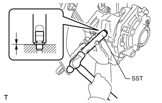
INSTALL TRANSFER CASE OIL SEAL RH
-
*1 Transfer Case Oil Seal RH Using SST and a hammer, tap in a new transfer case oil seal RH as shown in the illustration.
- SST
- 09316-60011 ( 09316-00011 )
Drive in depth (A) 7.5 to 8.5 mm (0.296 to 0.334 in.) Note
-
Tap the transfer case oil seal RH uniformly so that the transfer case oil seal RH is straight.
-
Do not tap the transfer case oil seal RH in too far.
-
-
INSTALL TRANSFER CASE BREATHER PLUG
-
Using SST, tap in a new transfer case breather plug until it meets the transfer case.
- SST
- 09612-10093 ( 09612-10061 )
-
-
INSTALL NO. 2 TRANSFER CASE PLUG
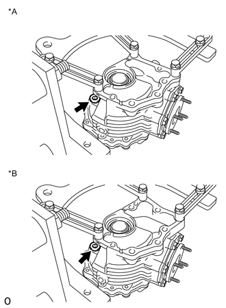
*A for CVT *B for Automatic Transaxle and Manual Transaxle
-
Using a 10 mm socket hexagon wrench, install a new gasket and the No. 2 transfer case plug (filler plug).
- Torque:
- 39 N*m { 398 kgf*cm, 29 ft.*lbf }
-
-
INSTALL TRANSFER DRAIN PLUG
*A for CVT *B for Automatic Transaxle and Manual Transaxle
-
Using a 10 mm socket hexagon wrench, install a new gasket and the transfer drain plug.
- Torque:
- 39 N*m { 398 kgf*cm, 29 ft.*lbf }
-
-
INSTALL NO. 1 TRANSFER CASE PLUG
-
Install a new gasket and the No. 1 transfer case plug.
- Torque:
- 49 N*m { 500 kgf*cm, 36 ft.*lbf }
-
-
REMOVE TRANSFER ASSEMBLY
-
*A for CVT *B for Automatic Transaxle and Manual Transaxle Remove the transfer assembly from the overhaul attachment.
-
-
INSTALL TRANSFER AND TRANSAXLE SETTING STUD BOLT
-
Clean the bolt holes.
-
*A for CVT *B for Automatic Transaxle and Manual Transaxle *a Transfer Side *b Toyota Genuine Adhesive 1324 Using 2 nuts, install the 4 stud bolts in the locations shown in the illustration.
- Torque:
- 39.2 N*m { 400 kgf*cm, 29 ft.*lbf }
Note
Install the shorter threaded part of each stud bolt to the transfer side.
-