DYNAMIC TORQUE CONTROL 4WD/AWD SYSTEM 4WD Control Switch Circuit
DESCRIPTION
The 4WD ECU assembly changes the control mode in response to "Auto Mode" and "Lock Mode" signals from the 4WD/AWD lock switch (differential lock switch).
WIRING DIAGRAM
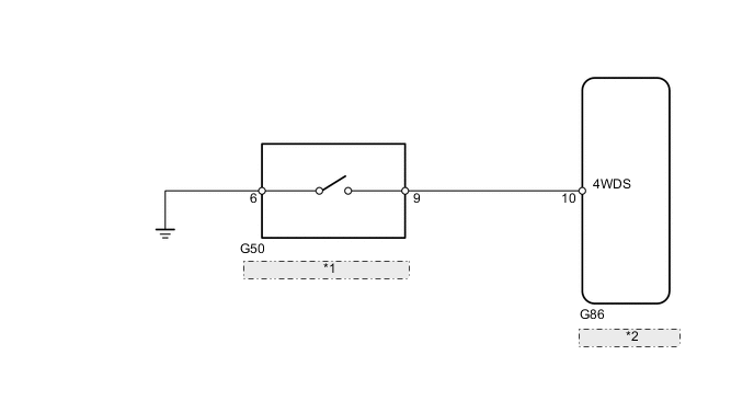
| *1 | 4WD/AWD Lock Switch (Differential Lock Switch) |
| *2 | 4WD ECU Assembly |
CAUTION / NOTICE / HINT
PROCEDURE
-
INSPECT DIFFERENTIAL LOCK SWITCH
-
Remove the 4WD/AWD lock switch (differential lock switch).
-
Inspect the 4WD/AWD lock switch (differential lock switch).
Result Proceed to OK NG
NG 
REPLACE DIFFERENTIAL LOCK SWITCH Click here
OK 
-
-
CHECK HARNESS AND CONNECTOR (DIFFERENTIAL LOCK SWITCH - BODY GROUND)
-
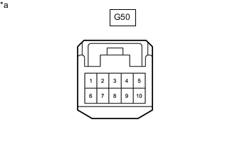
*a Front view of wire harness connector
(to 4WD/AWD Lock Switch [Differential Lock Switch])
Measure the resistance according to the value(s) in the table below.
Standard Resistance Tester Connection Condition Specified Condition G50-6 - Body ground Always Below 1 Ω Result Proceed to OK NG
NG
REPAIR OR REPLACE HARNESS OR CONNECTOR
OK
-
-
CHECK HARNESS AND CONNECTOR (DIFFERENTIAL LOCK SWITCH - 4WD ECU ASSEMBLY)
-
Reinstall the 4WD/AWD lock switch (differential lock switch).
-
Disconnect the 4WD ECU assembly connector.
-
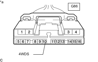
*a Front view of wire harness connector
(to 4WD ECU Assembly)
Measure the resistance according to the value(s) in the table below.
Standard Resistance Tester Connection Switch Condition Specified Condition G86-10 (4WDS) - Body ground 4WD/AWD lock switch on (Push) Below 1 Ω 4WD/AWD lock switch off (Release) 10 kΩ or higher Result Proceed to OK NG
OK
REPLACE 4WD ECU ASSEMBLY Click here
NG
REPAIR OR REPLACE HARNESS OR CONNECTOR
-