DYNAMIC TORQUE CONTROL 4WD/AWD SYSTEM Pattern Select Switch Sport Mode Circuit
DESCRIPTION
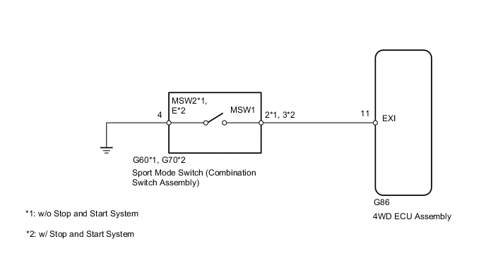
The 4WD ECU assembly switches from normal mode to sport mode when a sport mode ON signal is input from the sport mode switch (combination switch assembly).
WIRING DIAGRAM
CAUTION / NOTICE / HINT
PROCEDURE
-
INSPECT COMBINATION SWITCH ASSEMBLY
-
Remove the sport mode switch (combination switch assembly).
-
Ispect the sport mode switch (combination switch assembly).
Result Proceed to OK NG
NG 
REPLACE COMBINATION SWITCH ASSEMBLY Click here
OK 
-
-
CHECK HARNESS AND CONNECTOR (COMBINATION SWITCH ASSEMBLY - BODY GROUND)
-
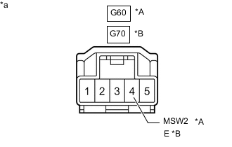
*A w/o Stop and Start System *B w/ Stop and Start System *a Front view of wire harness connector
(to Sport Mode Switch [Combination Switch Assembly])
Measure the resistance according to the value(s) in the table below.
Standard Resistance w/o Stop and Start System Tester Connection Condition Specified Condition G60-4 (MSW2) - Body ground Always Below 1 Ω w/ Stop and Start System Tester Connection Condition Specified Condition G70-4 (E) - Body ground Always Below 1 Ω Result Proceed to OK NG
NG
REPAIR OR REPLACE HARNESS OR CONNECTOR
OK
-
-
CHECK HARNESS AND CONNECTOR (COMBINATION SWITCH ASSEMBLY - 4WD ECU ASSEMBLY)
-
Reinstall the sport mode switch (combination switch assembly).
-
Disconnect the 4WD ECU assembly connector.
-
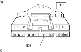
*a Front view of wire harness connector
(to 4WD ECU Assembly)
Measure the resistance according to the value(s) in the table below.
Standard Resistance Tester Connection Condition Specified Condition G86-11 (EXI) - Body ground Sport mode switch on (Push) Below 1 Ω Sport mode switch off (Release) 10 kΩ or higher Result Proceed to OK NG
OK
REPLACE 4WD ECU ASSEMBLY Click here
NG
REPAIR OR REPLACE HARNESS OR CONNECTOR
-