DYNAMIC TORQUE CONTROL 4WD/AWD SYSTEM, Diagnostic DTC:C1241/94

| DTC Code | DTC Name |
|---|---|
| C1241/94 | Low Power Supply Voltage |
DESCRIPTION
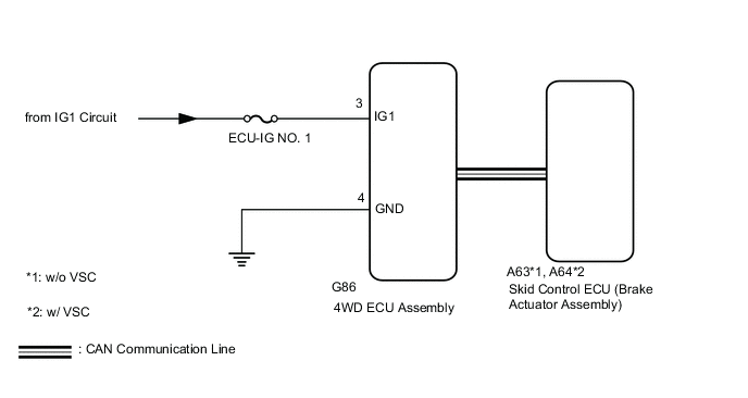
If a malfunction in the power source circuit occurs, or a malfunction in communication with the skid control ECU (brake actuator assembly) or in a speed sensor occurs, the 4WD ECU assembly will prohibit operations by the fail-safe function.
| DTC No. | Detection Item | DTC Detection Condition | Trouble Area |
|---|---|---|---|
| C1241/94 | Low Power Supply Voltage |
|
|
WIRING DIAGRAM
CAUTION / NOTICE / HINT
PROCEDURE
-
CHECK FOR DTC (CAN COMMUNICATION SYSTEM AND BRAKE CONTROL SYSTEM)
-
Check if CAN communication system DTCs are output.
for LHD: Click here
for RHD: Click here
-
Start the engine.
-
Drive the vehicle, accelerate to a speed of 3 km/h (2 mph) or more for 60 seconds or more, and check if the speed sensor DTC (brake control system DTC) is output.
w/o VSC: Click here
w/ VSC: Click here
Chassis > ABS/VSC/TRC > Trouble CodesResult Result Proceed to Neither CAN communication system DTC nor speed sensor DTC (brake control system DTC) is output A CAN communication system DTC is output (for LHD) B CAN communication system DTC is output (for RHD) C Speed sensor DTC (brake control system DTC) is output (w/o VSC) D Speed sensor DTC (brake control system DTC) is output (w/ VSC) E
B 
GO TO CAN COMMUNICATION SYSTEM (HOW TO PROCEED WITH TROUBLESHOOTING) Click here
C
GO TO CAN COMMUNICATION SYSTEM (HOW TO PROCEED WITH TROUBLESHOOTING) Click here
D
REPAIR CIRCUIT INDICATED BY OUTPUT CODE (BRAKE CONTROL SYSTEM) Click here
E
REPAIR CIRCUIT INDICATED BY OUTPUT CODE (BRAKE CONTROL SYSTEM) Click here
A 
-
-
INSPECT BATTERY
-
Check the battery voltage.
Standard voltage 11 to 14 V Result Proceed to OK NG (for 2AR-FE) NG (for 2AD-FHV) NG (for 2AD-FTV) NG (for 3ZR-FAE) NG (for 3ZR-FE)
NG (for 2AR-FE)
CHECK CHARGING SYSTEM Click here
NG (for 2AD-FHV)
CHECK CHARGING SYSTEM Click here
NG (for 2AD-FTV)
CHECK CHARGING SYSTEM Click here
NG (for 3ZR-FAE)
CHECK CHARGING SYSTEM Click here
NG (for 3ZR-FE)
CHECK CHARGING SYSTEM Click here
OK
-
-
CHECK HARNESS AND CONNECTOR (IG1 TERMINAL)
-
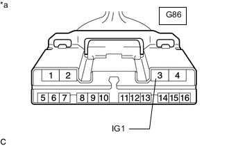
*a Front view of wire harness connector
(to 4WD ECU Assembly)
Disconnect the 4WD ECU assembly connector.
-
Turn the ignition switch to ON.
-
Measure the voltage according to the value(s) in the table below.
Standard Voltage Tester Connection Switch Condition Specified Condition G86-3 (IG1) - Body ground Ignition switch ON 11 to 14 V Result Proceed to OK NG
NG
REPAIR OR REPLACE HARNESS OR CONNECTOR
OK
-
-
CHECK HARNESS AND CONNECTOR (GND TERMINAL)
-
Turn the ignition switch off.
-
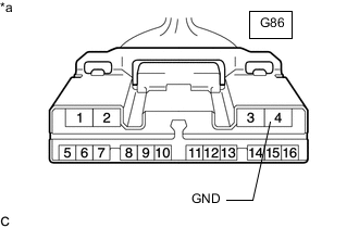
*a Front view of wire harness connector
(to 4WD ECU Assembly)
Measure the resistance according to the value(s) in the table below.
Standard Resistance Tester Connection Condition Specified Condition G86-4 (GND) - Body ground Always Below 1 Ω Result Proceed to OK NG
NG
REPAIR OR REPLACE HARNESS OR CONNECTOR
OK
-
-
RECONFIRM DTC
-
Clear the DTC.
Chassis > Four Wheel Drive > Clear DTCs -
Start the engine.
-
Drive the vehicle, accelerate to a speed of 3 km/h (2 mph) or more, and check if the same DTC is output.
Chassis > Four Wheel Drive > Trouble CodesResult Proceed to DTC is output DTC is not output Tech Tips
Reinstall the sensor, connectors, etc. and restore the vehicle to its prior condition before rechecking DTCs.
DTC is output
REPLACE 4WD ECU ASSEMBLY Click here
DTC is not output
CHECK FOR INTERMITTENT PROBLEMS Click here
-